Installation procedure for 8x DI/O uFM
module
About this task
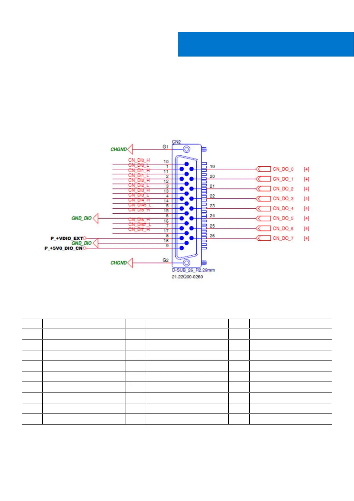
Pin mappings for the DI/O connector are shown in the following figure and table.
Figure 123. DI/O connector pin locations
Table 23. Digital I/O uFM module pin definitions
Pin Signal Pin Signal Pin Signal
1 DI0_L 10 DI0_H 19 DO0
2 DI1_L 11 DI1_H 20 DO1
3 DI2_L 12 DI2_H 21 DO2
4 DI3_L 13 DI3_H 22 DO3
5 DI4_L/DI5_L 14 DI4_H 23 DO4
6 GND_DIO 15 DI5_H 24 DO5
7 DI6_L/DI7_L 16 DI6_H 25 DO6
8 +VDIO_EXT 17 DI7_H 26 DO7
9 +5V0_DIO 18 GND_DIO - -
Installation requires the removal of COM3 and COM4 ports. The four-port COM cable will be replaced with an included dual-port
COM cable.
VIII
72 Installation procedure for 8x DI/O uFM module