Installation procedure for 4G expansion
module
About this task
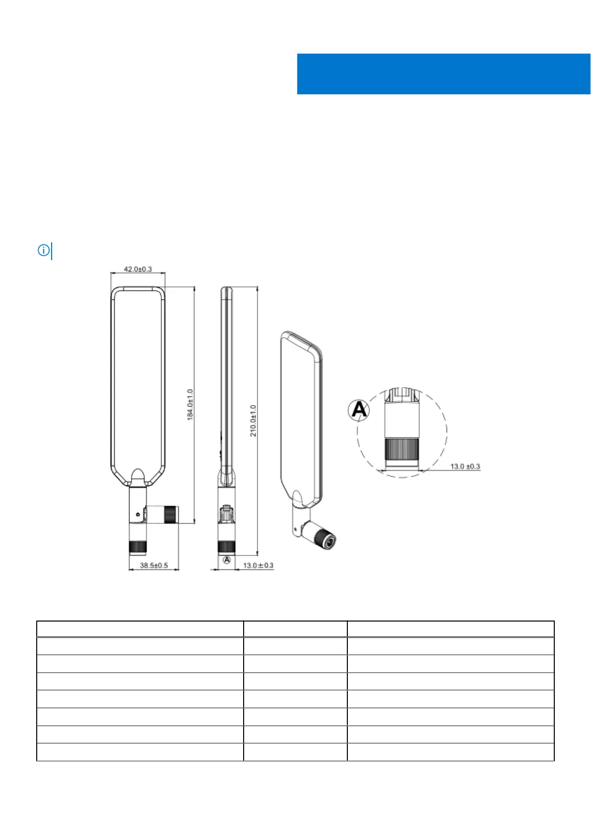
Installation of the 4G expansion module requires an additional heat sink to ensure performance.
Use the paddle-style antennas that are included with the expansion kit. The following figure shows the dimensions of the
antenna.
NOTE: Perform this procedure in an electrostatic discharge (ESD) controlled environment.
Figure 11. 4G/5G/LTE antenna (dimensions in mm)
Table 3. Expansion module packing list - 4G
Item Quantity Notes
Screw M3 x 6L 1 Torque required: 4.0 kgf.cm
Screw M3 x 4L 7 Torque required: 4.0 kgf.cm
Standoff H7.8 1 Torque required: 4.5 kgf.cm
Standoff H19.5 2 Torque required: 4.5 kgf.cm
Bracket 1 -
4G M.2 1 -
SMA cable 3 Torque required: 8.0 kgf.cm
II
Installation procedure for 4G expansion module 11