Table 24. Expansion module packing list
Item Quantity Notes
Screw M3 x 4L 12 Torque required: 4.0 kgf.cm
Screw M2.5 x 6L 2 Torque required: 3.0 kgf.cm
Screw M3 x 6L 2 Torque required: 4.0 kgf.cm
Standoff H4 6 Torque required: 4.5 kgf.cm
Standoff H7 2 Torque required: 4.5 kgf.cm
Nut M3 4 Torque required: 4.0 kgf.cm
Cable tie 2 -
Rubber cap 2 -
Sheet metal I/O panel 1 -
Bracket 1 -
DI/O PCBA 1 -
Dual-port COM cable 1 -
DI/O cable 1 -
Table 25. Tools needed
Tool Notes
Phillips head screwdriver Small size
Nut driver 5 mm
Steps
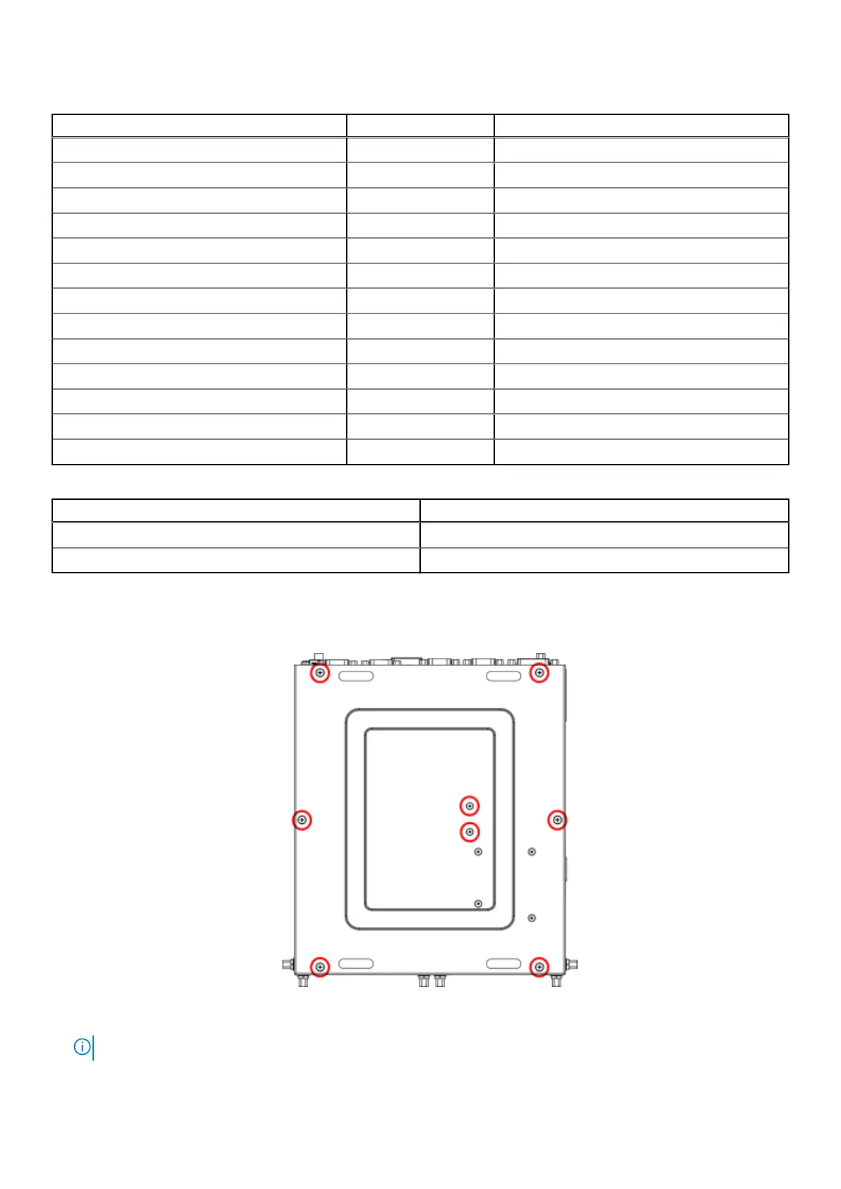
1. Remove the eight screws from the bottom panel of the EGW-5200, as shown in the following figure, and remove the bottom
panel.
Figure 124. Bottom panel screw locations
NOTE: If 4G or 5G is installed, you must also remove the remaining four screws from the bottom panel.
Installation procedure for 8x DI/O uFM module 73