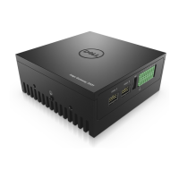
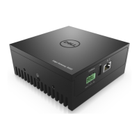
2. Remove the screws and standoffs of the front I/O panel, as shown in the following figure.
Figure 125. I/O panel screw and standoff locations
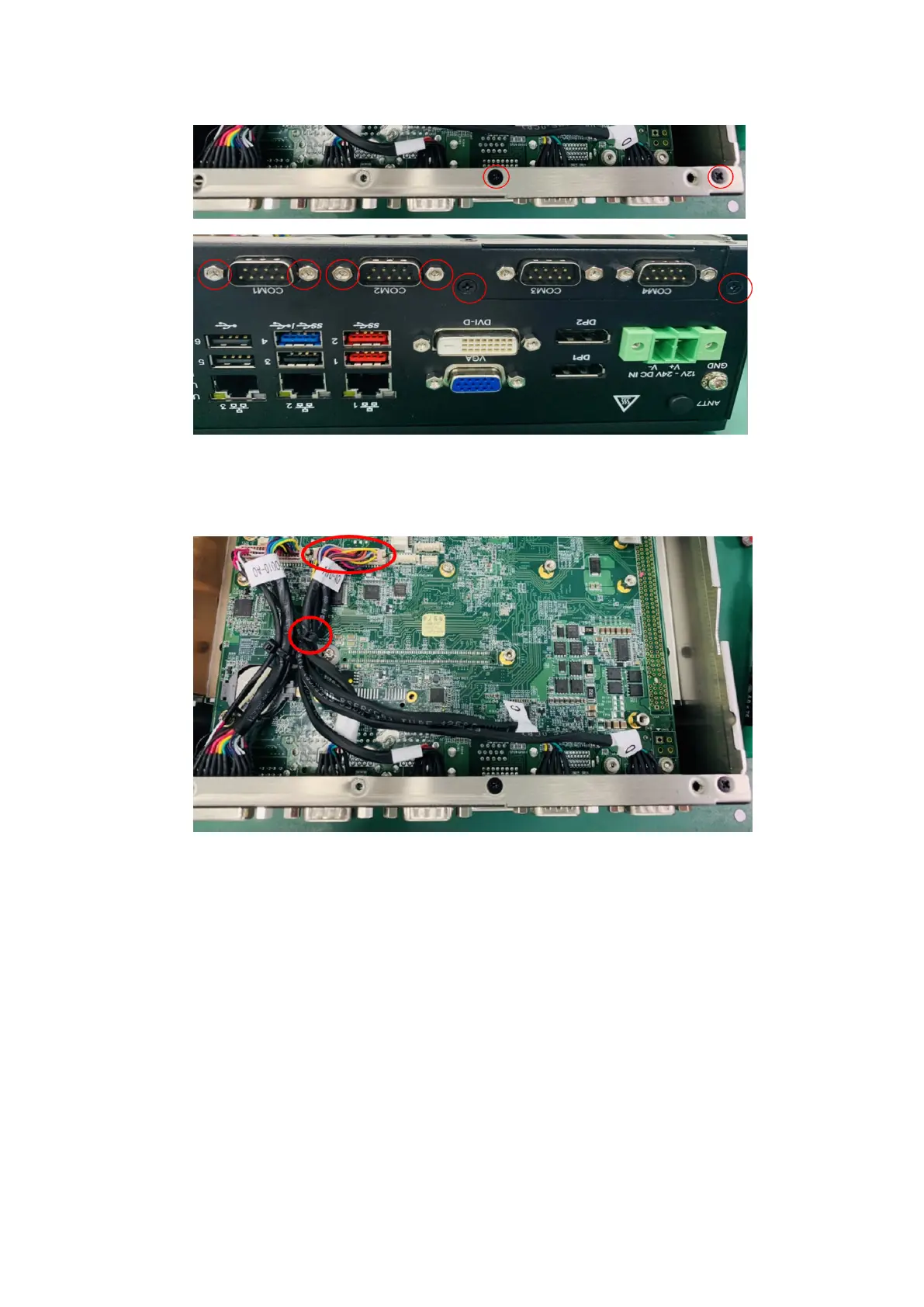
3. Disconnect the four-port COM cable from the motherboard header and from the front I/O panel, and cut the cable tie, as
shown in the following figure.
Figure 126. Disconnect COM port cable
4. Install the new dual-port COM cable (included). Connect to the front I/O panel with the port labeled A to COM1 and B
to COM2, use four H4 standoffs to secure the ports to the fron panel, then connect the other end of the cable to the
motherboard header.
74
Installation procedure for 8x DI/O uFM module