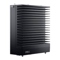
Figure 26. Standoff screw hole locations
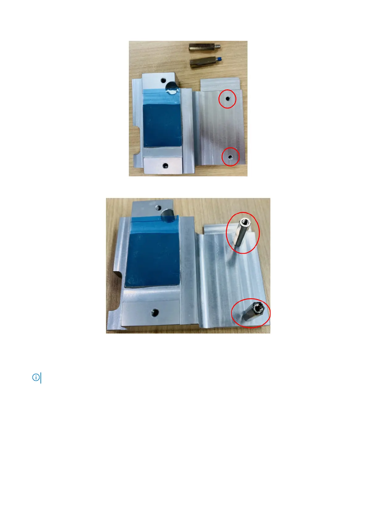
Figure 27. Standoff screws assembled
12. To apply the heat sink onto the M.2 module, use one M3 x 6L screw to secure the heat sink into position, as shown in the
following figure, then use three M3 x 4L screws to secure the heat sink to the side panel.
NOTE: Remove the protective film from the thermal pad material before installing.
20 Installation procedure for 4G expansion module