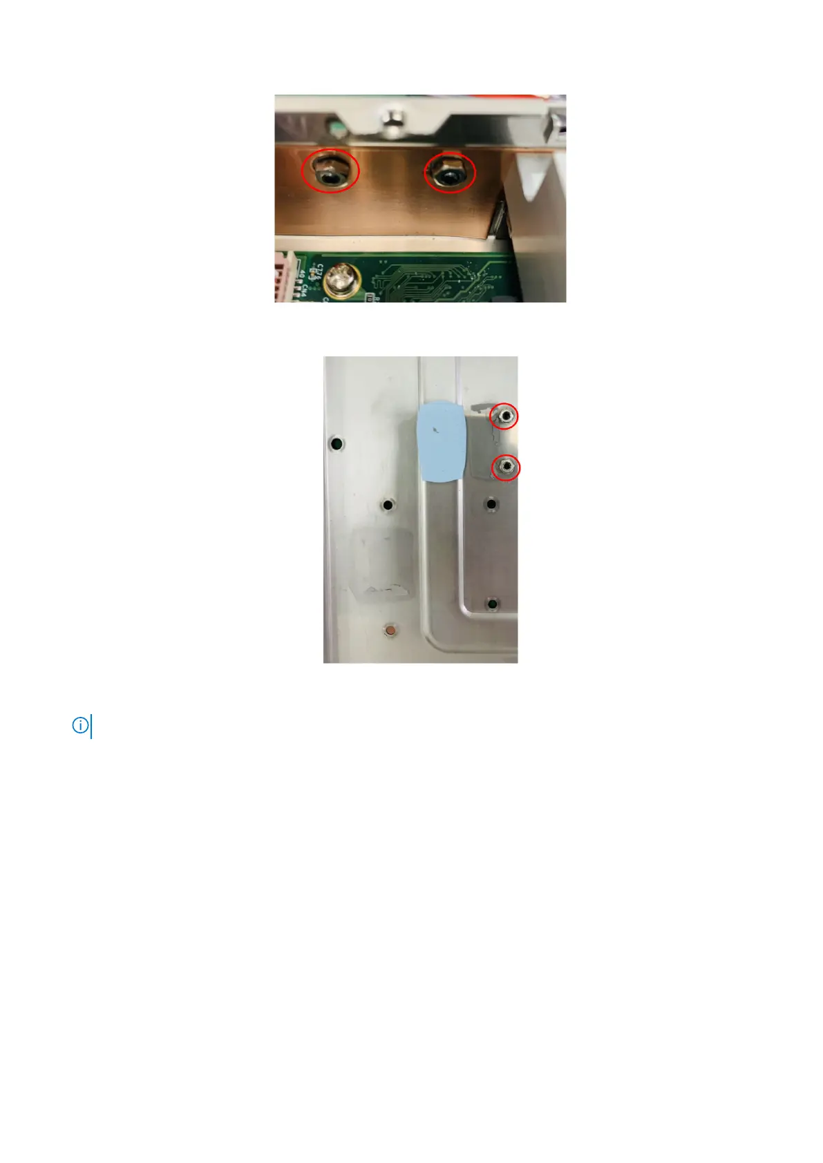
Figure 96. Install screws and nuts on side panel
Figure 97. Install screws and nuts on bottom panel
NOTE: M3 x 4L screws and M3 nuts are included in the Expansion Module contents.
7. Remove the screws and standoffs of the front I/O panel, as shown in the following figure. Remove the four-port COM cable
from the front I/O panel.
58
Installation procedure for 2x GbE LAN uFM module