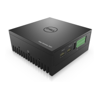
Figure 110. Motherboard standoffs and WiFi cable connectors
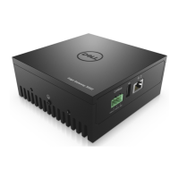
4. Disconnect the four-port COM cable from the motherboard header and from the front I/O panel, and cut the cable tie, as
shown in the following figure.
Figure 111. Disconnect COM port cable
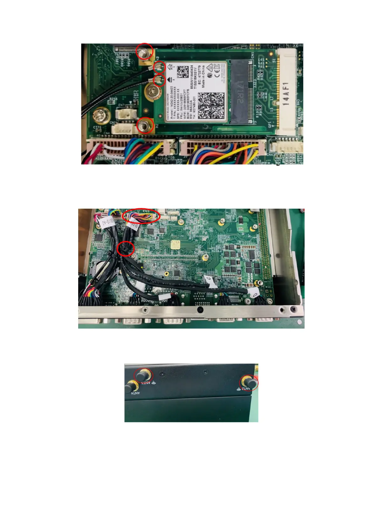
5. Remove the SMA cables from the ANT2 and ANT3 antenna ports, as shown in the following figure.
Figure 112. Remove SMA cables
6. Install screws and nuts to holes (previously used to secure the heat sink) in the side panel and bottom panel, as shown in the
following figures.
66
Installation procedure for 2x Canbus uFM module