126 Adding and Replacing Parts
8
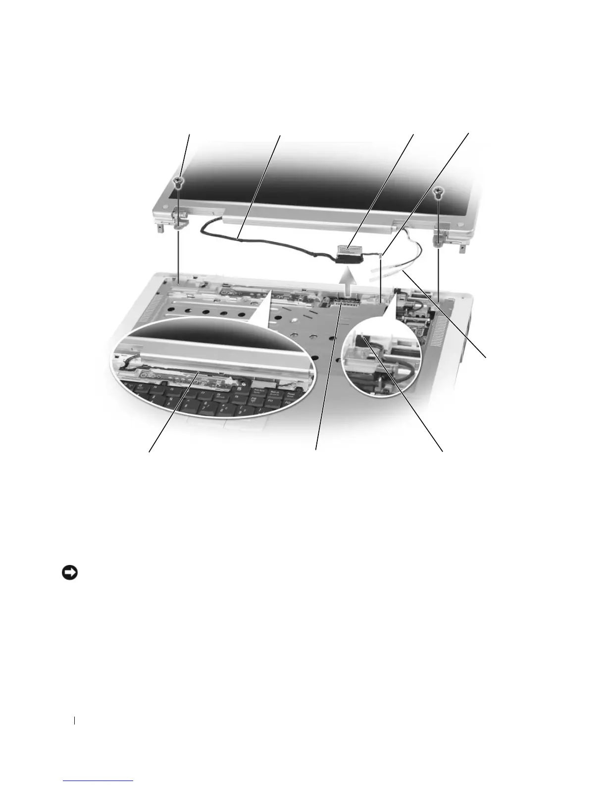
Lift the display up and away from the computer.
NOTICE: The standby switch is fragile and easily broken. Avoid knocking the switch when removing and replacing
the display.
When you replace the display, ensure that the display cable is lying flat in the display cable channel and
securely tucked underneath the tabs.
Also, ensure that the antenna cables are not twisted and that they are lying flat in the antenna cable clip.
1 screws (6) 2 display cable 3 display cable pull-tab
4 grounding-wire screw 5 antenna cables 6 standby switch
7 display cable connector on
system board
8 display cable channel
7
2
8
3
5
1 4
6