164 Installing Blade Components
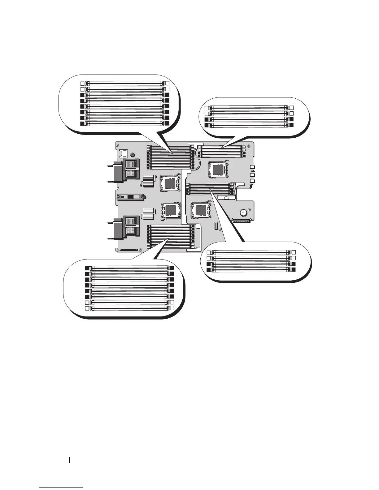
Figure 3-13. Memory Locations – PowerEdge M905
General Memory Module Installation Guidelines – PowerEdge M905
To ensure optimal performance of your system, observe the following
guidelines when configuring your system memory:
•Memory modules m
ust be installed in pairs
, beginning with the first two
sockets in each set of memory modules. These sockets are marked by white
retention levers.
• All memory modules in the blade must be identical in speed and
technology. The memory modules in each pair must be the same size.