Dell DCS-1130 Setup and Features Information
Back-Panel Features and Indicators | Page 7
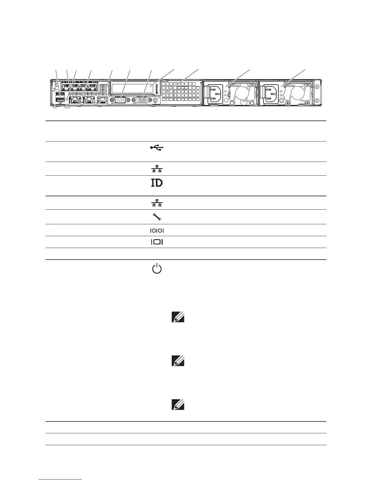
Back-Panel Features and Indicators
Figure 3. Back Panel
1 2
ID
31 4 5 6 7
11109
8
2
Item Indicator, Button, or
Connector
Icon Description
1 USB connectors (2) Connect USB devices to the system. e ports are
USB 2.0-compliant.
2 RJ-45 (4) Embedded 10/100/1000 NIC connectors.
3 System identication
indicator
Lights amber when the system needs attention due
to a problem.
4 Ethernet connectors (2) Embedded 10/100/1000 NIC connectors.
5 KVM over IP Port Dedicated management port.
6 Serial connector Connects a serial device to the system.
7 Video connector Connects a VGA display to the system.
8 Single channel optic interface In PCIe slot.
9 Power-on indicator/
power button
e power-on indicator lights when the system
power is on.
e power button controls the DC power supply
output to the system.
NOTE: When powering on the system, the video
monitor can take from several seconds to over
2 minutes to display an image, depending on the
amount of memory installed in the system.
NOTE: On ACPI-compliant operating systems,
turning off the system using the power button
causes the system to perform a graceful shut-
down before power to the system is turned off.
NOTE: To force an ungraceful shutdown, press
and hold the power button for five seconds.
10 Power supply 2 (PS2) 470W
11 Power supply 1 (PS1) 470W