Install the S55 | 21
To install an optional module, follow the steps below:
Install the SFP and SFP+ optics
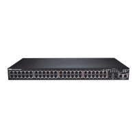
The S55 has 4 SFP optical ports in the PSU side of the chassis in addition to the optional SFP+ optical
modules. To install SFP or SFP+ optics into an open port, follow the steps below:
WARNING: Electrostatic discharge (ESD) damage can occur if components are mishandled. Always wear an ESD-
preventive wrist or heel ground strap when handling the S55 and its components.
WARNING: Follow all warning labels when working with optical fibers. Always wear eye protection when
working with optical fibers. Never look directly into the end of a terminated or unterminated fiber or connector
as it may cause eye damage.
NOTE: For details on Dell Force10 supported optics, refer to
http://www.force10networks.com/products/
specifications.asp
Connect stacking ports (optional)
Rack-mount the switches or insert them into a cabinet before you make your stacking port connections.
Insert one end of the stacking cable into a stacking port, and insert the other end into a stacking port of the
adjacent switch. Hand-tighten all captive screws to ensure that the cable is secure in the connector.
Dell Force10 supports stacking connections for up to 12 S55 switches, to configure as a unified system.
CAUTION: The S55 system does not stack with other S-Series systems.
You can connect the switches while they are powered down or up. Both ring topology and cascade
topology connections are supported (
Figure 4-1
). Stacking ports are bi-directional.
When using the 2-port 12G stacking module, the stacking ports are labeled 48-49 on the PSU side.
NOTE: Use only the supported stacking cables for connecting the switches.
Step Task
1 Remove the faceplate covering the module slot on PSU side of the S55.
2 Remove the module from its packaging and slide the module into the slot.
3 Secure the captive screws on the sides of the module.
Step Task
1 Position the SFP or SFP+ so it is in the correct position. (The optic has a key that prevents it from being inserted
incorrectly.)
2 Insert the optic into the port until it gently snaps into place.