Steps
1 Open the latch and disconnect the hard drive cable from the system board.
2 Open the latch and disconnect the power-button cable from the system board.
3 Open the latch and disconnect the battery cable from the system board.
4 Open the latch and disconnect the keyboard cable from the system board.
5 Disconnect the speaker cable from the system board.
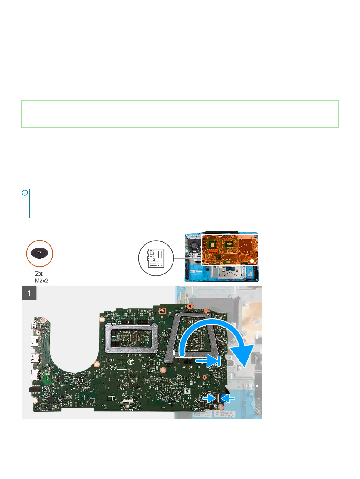
6 Remove the two (M2x2) screws that secure the system board to the palm-rest and keyboard assembly.
7 Turn the system board over and disconnect the I/O board cable from the system board.
Identifier GUID-BA27C213-B7F1-41F6-B836-E6C76C377150
Status Released
Installing the system board
Prerequisite
If you are replacing a component, remove the existing component before performing the installation procedure.
About this task
The following image indicates the location of the system board and provides a visual representation of the installation procedure.
NOTE
:
The I/O board connector is located underneath the system board. Turn the system board over and connect the I/O board cable to the
system board.
48 Removing and installing components