11. SATA3 connector (white)
12. SATA0 connector (blue)
13. M.2 WLAN connector
14. M.2 PCIe SSD connector
15. PCIe x4 (Slot4)
16. PCIe x16 (Slot3)
17. PCIe x1 (Slot2)
18. PCIe x1 (Slot1)
19. Type-C connector
20. Processor socket
21. Keyboard and Mouse serial connector
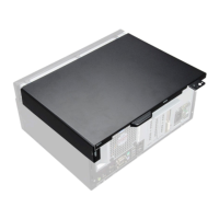
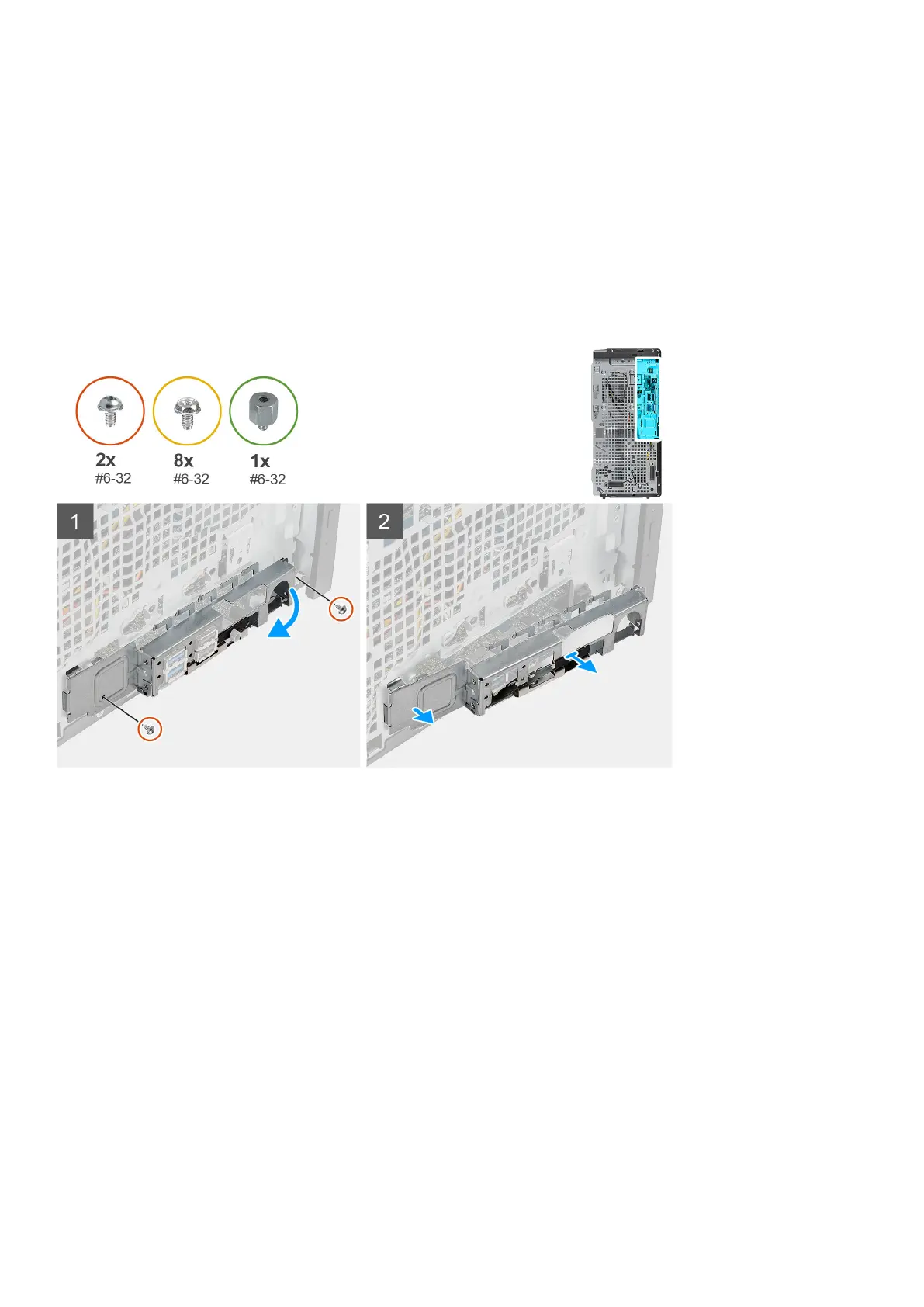
The following images indicate the location of the system board and provide a visual representation of the removal procedure.
58 Removing and installing components