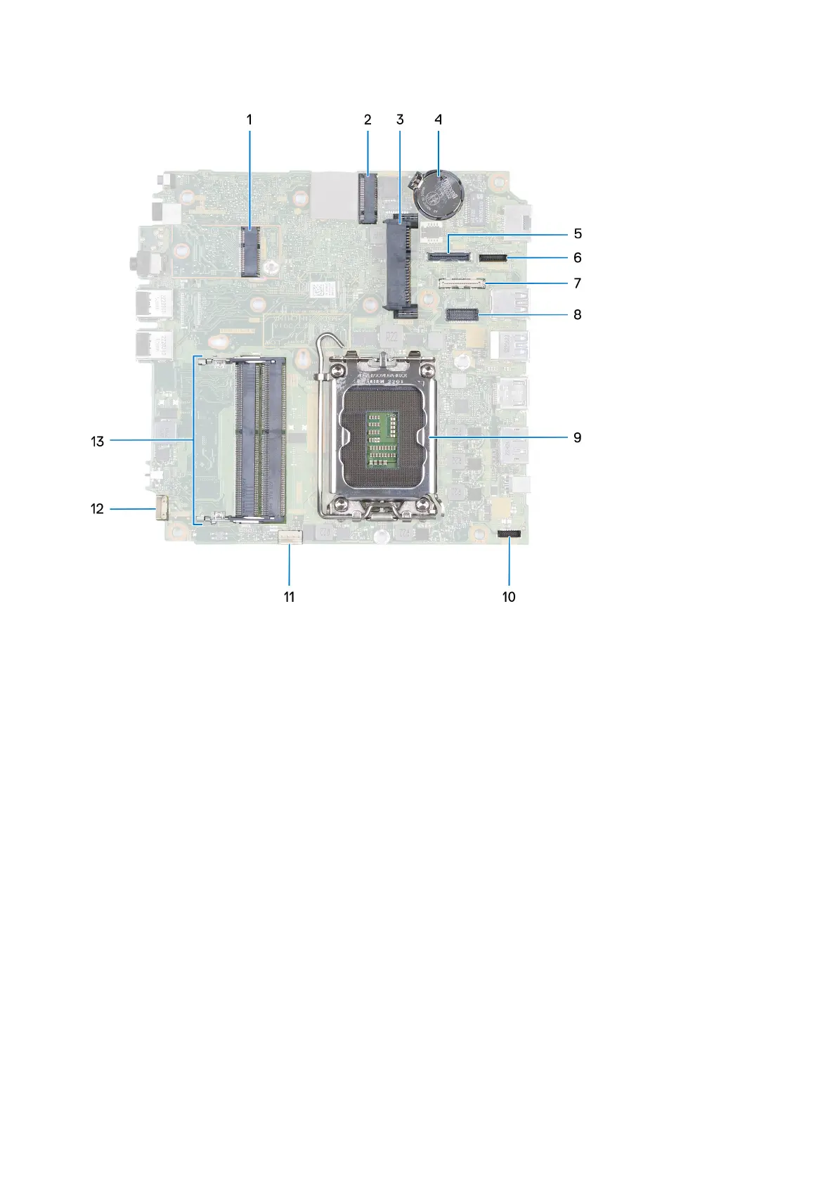
1. M.2 WLAN connector
2. M.2 SSD PCIe connector (2230/2280)
3. 2.5-inch hard-drive connector
4. Coin-cell battery
5. Optional video connector (VGA Port/DisplayPort 1.4a (HBR3)/HDMI 2.1 Port/Type-C DisplayPort)
6. Type-C signal connector
7. Type-C USB connector
8. Optional PS/2, serial port connector
9. Processor socket
10. Type-C power connector
11. Fan connector
12. Internal speaker connector
13. Memory-module slots
The following image(s) indicate the location of the system board and provides a visual representation of the installation
procedure.
70
Removing and installing Field Replaceable Units (FRUs)