P992 (E) 1-6
4
5
7
4
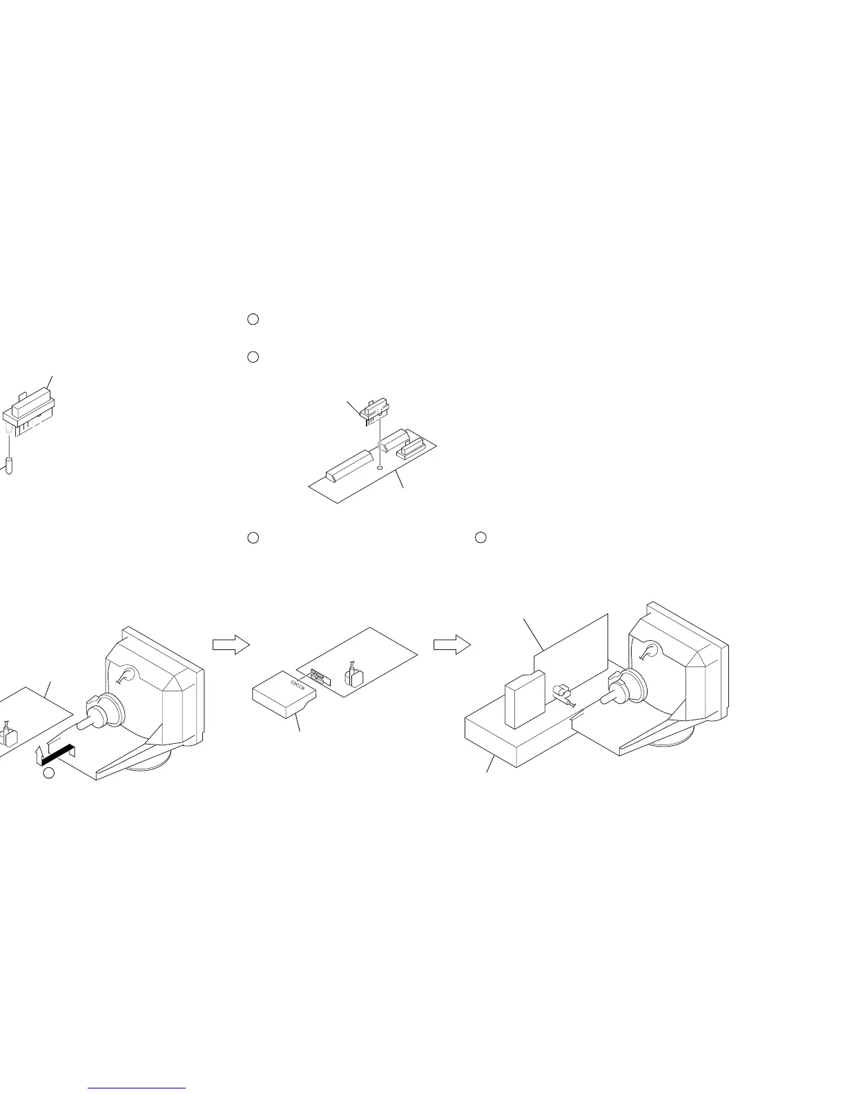
Remove the D board.
D board
5
Remove the Video block assembly.
1
Prepare a connector (10Pin: Black) (1-766-921-11),
cut of the boss on the 10-pin side.
Adaptor board (XT Mount) is reconstructied to use for this set.
2
Remove the connector (17Pin: Black) (CN9997)
from Adaptor board (XT MOUNT) (A-1391-123-A).
3
Install the connector (10Pin: Black) onto XT Mount.
6
Install the Adaptor board
(XT MOUNT) (A-1391-123-A).
7
Lay the Video block assembly.
Video block assembly
Connector (10Pin: Black)
Boss
Connector
(10Pin: Black)
Adoptor board
(XT mount)
Video block assembly
8
Install the video block assembly.
9
Put a box which is about 15cm in height
under the D board to fix it.
(Please disconnect the CN 701 first.)
D board
Box
6
1-6. SERVICE POSITION