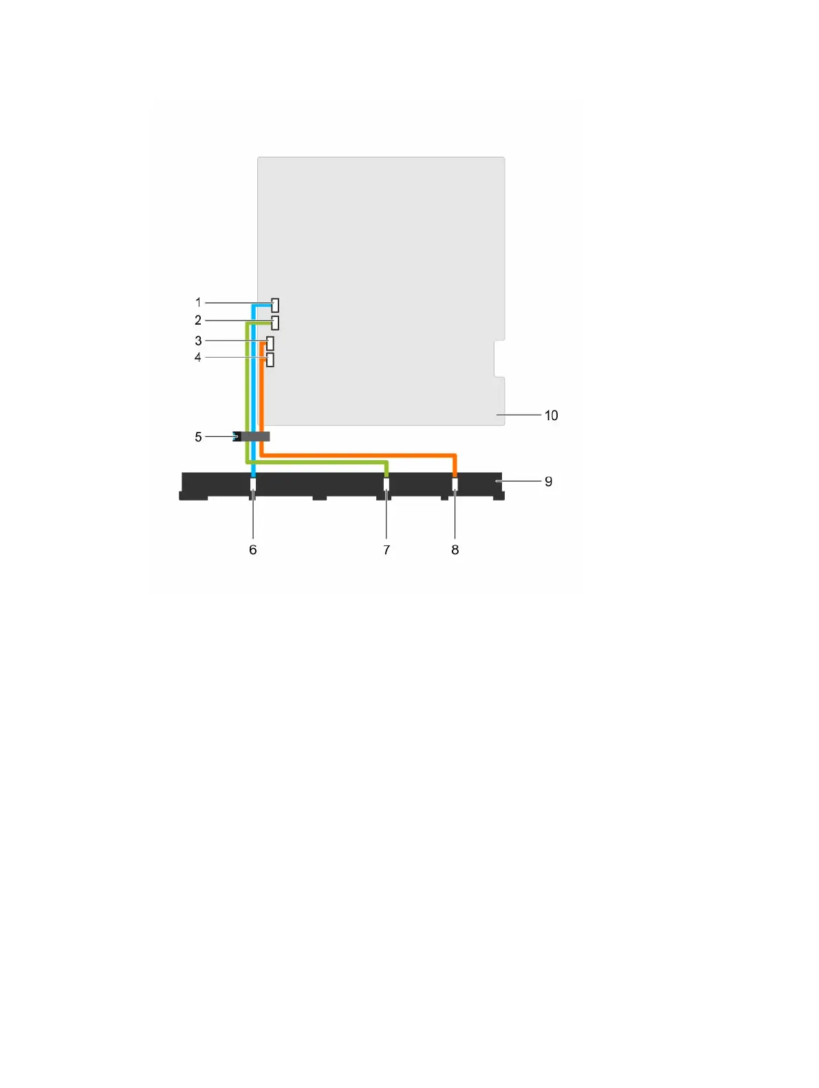
Figure 83. Cabling diagram—Ten 2.5 inch SAS/SATA backplane
1. SW_RAID_A connector on the system
board
2. SW_RAID_B connector on the system
board
3. SATA_hard drive8 connector on the
system board
4. SATA_hard drive9 connector on the
system board
5. cable routing latch 6. SAS_A connector on the backplane
7. SAS_B connector on the backplane 8. SAS_C connector on the backplane
9. hard drive/SSD backplane 10. system board
Next steps
1. Install the hard drive backplane.
2. Install all the hard drives into their original slots.
3. Follow the procedure listed in the After working inside your system section.
167