Item Indicator, Button, or
Connector
Icon Description
video/VGA port, see the Technical specifications
section.
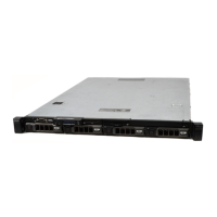
7 Ethernet port 2
Use the Ethernet port to connect Local Area
Networks (LANs) to the system. For more
information about the supported Ethernet ports,
see the Technical specifications section.
8 USB port
Use the USB 2.0 port to connect USB devices to
the system. This port is 4-pin, USB 2.0 compliant.
9 USB port
Use the USB 3.0 port to connect USB devices to
the system. These ports are 9-pin, USB 3.0
compliant.
10 System identification
button
Press the system ID button:
• To locate a particular system within a rack.
• To turn the system ID on or off.
NOTE: To reset the iDRAC (if not disabled in F2
iDRAC setup), press and hold the button for
more than 15 seconds.
NOTE: If the system stops responding during
POST, press and hold the system ID button
(for more than five seconds) to enter the BIOS
progress mode.
11 System identification
port
Use the system identification port to connect the
system status indicator assembly through the
optional cable management arm.
12 Ethernet port 3
Use the Ethernet port to connect Local Area
Networks (LANs) to the system. For more
information about the supported Ethernet ports,
see the Technical specifications section.
13 Ethernet port 4
14 Power supply unit (PSU) One 450 W cabled AC PSU.
NOTE: Cabled PSU is supported in systems
with cabled hard drives and the systems with
x4 backplane.
Diagnostic Indicators
The diagnostic indicators on the system front panel display error status during system startup.
Diagnostic indicators on the front panel
NOTE: The diagnostic indicators are not present if the system is equipped with an LCD display.
23