b. Secure the LED panel with the screws.
2. Insert the control panel module into the slot in the chassis and align the two screw holes on the
control panel module with the corresponding holes on the chassis.
3. Secure the control panel module with the screws.
4. Connect all the applicable cables to the control panel module.
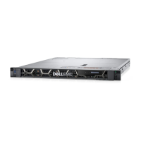
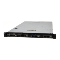
Figure 96. Installing the control panel module—four cabled hard-drive chassis
1. screw (2) 2. control panel module connector cable
3. control panel module 4. USB connector cable
5. control panel 6. LED-panel screw (2)
7. LED panel
179