device on the SCSI bus. Otherwise, attach one end of a SCSI cable to the
remaining port and the other end to the next device on the SCSI bus. Make
sure that the last device on the SCSI bus is properly terminated.
Note: Cables and terminators supporting Ultra160 should be used.
Note:
The host bus adapter should be LVD SCSI. A single-ended (SE) SCSI
host bus adapter will work, but will severely degrade performance,
and limit cable length. If there are any SE devices on the same SCSI
bus, the entire SCSI bus will negotiate down to SE speed and severely
degrade performance.
v For a Fibre Channel library, connect the host interface cable to the host or to
a switch.
v For a SAS library, connect the drive using a host interface cable to the host
HBA, or to an interposer as required. You can connect to either ports if you
have a dual port configuration. Unused SAS connectors do not need
termination.
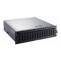
4.
Plug the network ethernet cable (
2
in Figure 1-13 on page 1-11, Figure 1-14 on
page 1-11, or 3 in Figure 1-15 on page 1-11) into the ethernet port on the back
panel of the library. If the ethernet connection is directly attached to a server or
laptop, a crossover ethernet cable may be required.
Note: It is the customer’s responsibility to supply the crossover ethernet cable
if one is required.
Connecting a Power Cord
Attention: This product can ONLY be used with an approved power cord for
your specific geographic region. Use of an unapproved power cord may result in:
v not meeting individual country specific safety requirements;
v overheating with potential personal injury and/or property damage; and
v a fracture resulting in the internal contacts being exposed, which potentially
could subject the user to a shock hazard.
For
every power supply in the library, complete the following steps.
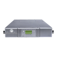
1. Plug one end of the power cord (
4
in Figure 1-13 on page 1-11, Figure 1-14 on
page 1-11, or 1 in Figure 1-15 on page 1-11) into each power supply connector
on the back panel of the library.
2. Plug the other end of each power cord into the nearest properly grounded
power outlet. Use separate power sources for each power supply for redundant
power.
Attention: To disconnect all power from the library, remove the power cord
from each outlet. The power button removes power from portions of the library
and the drives, but the power supplies still have AC power at their inputs.
3. Remove the protective plastic on the exterior surfaces of the library.
4. Turn ON the library using the power button. Check the Operator Control Panel
display to make sure the library is receiving power. If it is not, check the power
connections and your power source. During the Power-On Self Test (POST), all
four LEDs are illuminated briefly, followed by a flashing Ready LED. When the
initialization sequence is complete, the Home screen will be displayed.
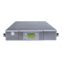
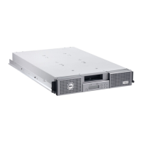
1-12 Getting Started with the Dell PowerVault TL2000 and TL4000 Tape Libraries
 Loading...