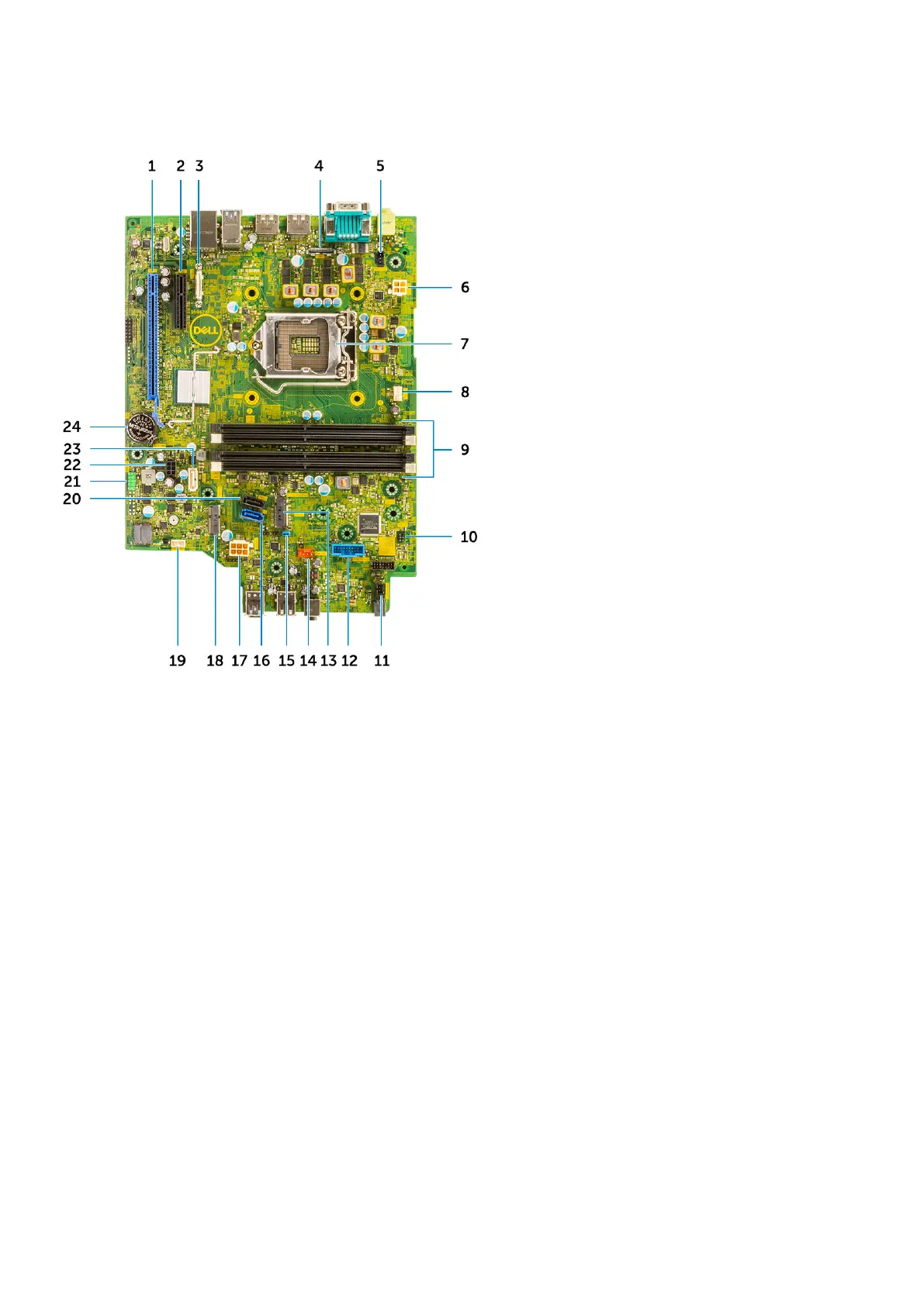
Motherboard layout
1. PCI-e x16 connector (slot 2) 2. PCI-e x4 connector (slot1—open ended x4 to support x16
3. USB Type-C connector 4. Video connector
5. Intrusion switch connector (Intruder) 6. CPU power connector (ATX_CPU)
7. Processor socket (CPU) 8. CPU fan connector
9. Memory slots (DIMM1, DIMM2, DIMM3, DIMM4) 10. Power switch connector (PWR_SW)
11. Remote PWR switch connector 12. Media card reader connector (Card_reader)
13. M.2 SSD card/Intel Optane connector 14. System fan connector
15. Clear password jumper (PASSWORD_CLR) 16. SATA 0 connector
17. PSU connector 18. M.2 WLAN connector
19. Internal speaker connector (INT_SPKR) 20. SATA 3 connector
21. Internal USB connector (FRONT_USB 22. SATA power connector (SATA_PWR)
23. SATA 2 connector 24. Coin cell battery
Side cover
Removing the side cover
1. Follow the procedure in Before working inside your computer.
2. To remove the cover:
a) Slide the release latch on the back side of your system until it gives a click sound to unlock the side cover [1].
b) Slide and lift the side cover from the system [2].
Removing and Installing components
19
 Loading...