Steps
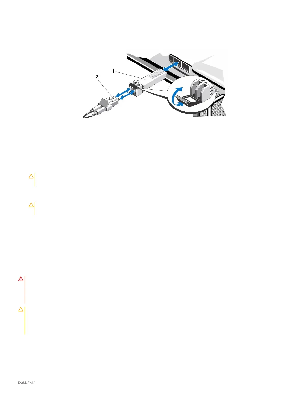
1 Position the transceiver module so that the key is oriented correctly to the port in the storage controller.
Figure 5. Install the SFP+ Transceiver Module
1 SFP+ transceiver module 2 Fiber-optic cable connector
2 Insert the transceiver module into the port until it is rmly seated and the latching mechanism clicks.
The transceiver modules are keyed so that they can be inserted only with the correct orientation. If a transceiver module does not
slide in easily, ensure that it is correctly oriented.
CAUTION
: To reduce the risk of damage to the equipment, do not use excessive force when inserting the transceiver
module.
3 Position the ber-optic cable so that the key (the ridge on one side of the cable connector) is aligned with the slot in the transceiver
module.
CAUTION
: Touching the end of a ber-optic cable damages the cable. Whenever a ber-optic cable is not connected,
replace the protective covers on the ends of the cable.
4 Insert the ber-optic cable into the transceiver module until the latching mechanism clicks.
Remove an SFP+ Transceiver Module
Complete the following steps to remove an SFP+ transceiver module from a storage controller.
Prerequisite
Use failover testing to make sure that the connection between host servers and the Storage Center remains up if the port is disconnected.
About this task
Read the following cautions and information before beginning the removal and replacement procedures.
WARNING
: To reduce the risk of injury from laser radiation or damage to the equipment, take the following precautions:
• Do not open any panels, operate controls, make adjustments, or perform procedures to a laser device other than those specied in
this document.
• Do not stare into the laser beam.
CAUTION: Transceiver modules can be damaged by electrostatic discharge (ESD). To prevent ESD damage to the transceiver
module, take the following precautions:
• Wear an antistatic discharge strap while handling modules.
• Place modules in antistatic packing material when transporting or storing them.
Steps
1 Remove the ber-optic cable that is inserted into the transceiver.
a Make sure the ber-optic cable is labeled before removing it.
b Press the release clip on the bottom of the cable connector to remove the ber-optic cable from the transceiver.
About the SCv3000 and SCv3020 Storage System
15
 Loading...