About this task
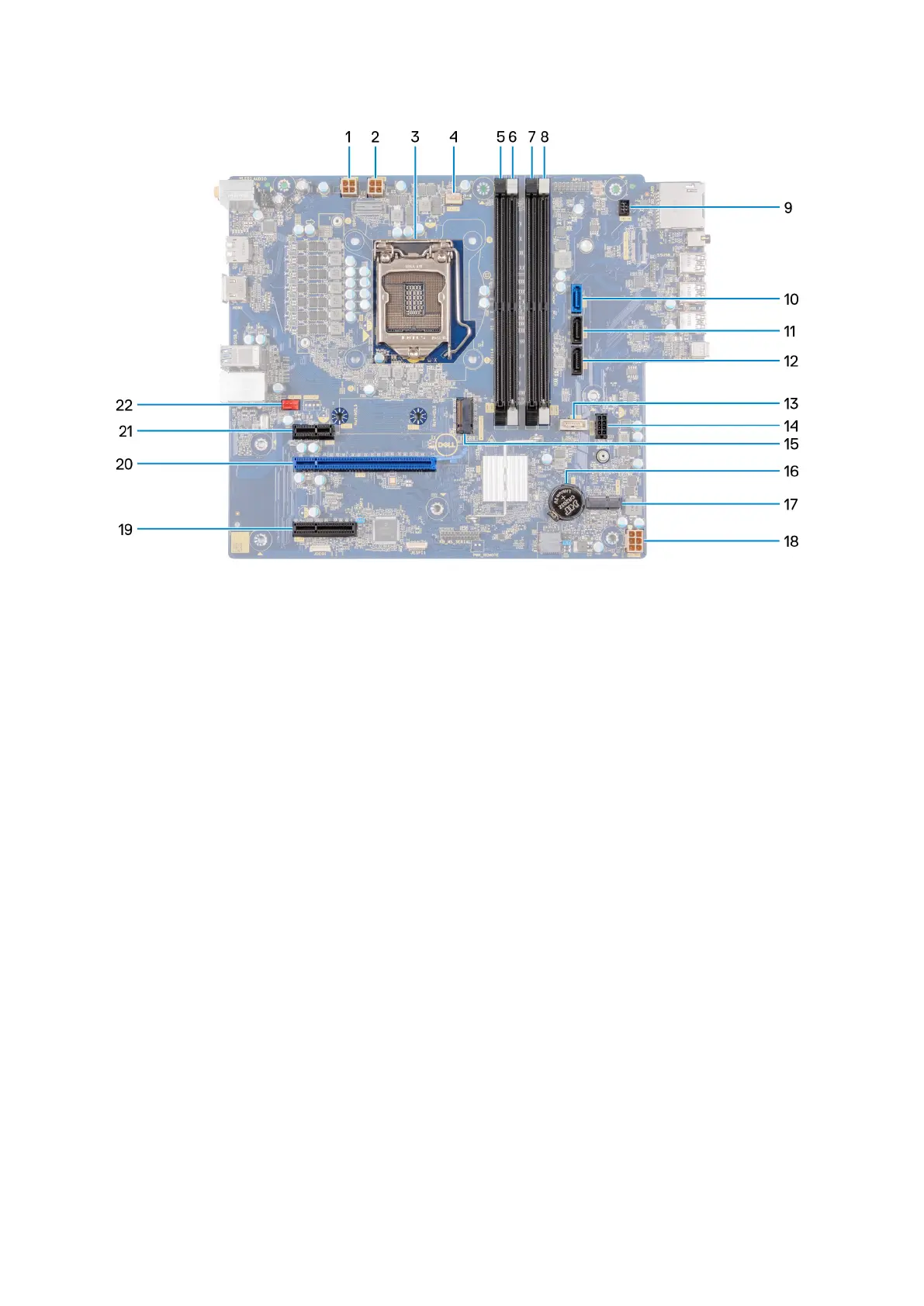
Figure 1. System-board components
1. processor power-cable connector (ATX CPU1)
2. processor power-cable connector (ATX CPU)
3. processor
4. processor-fan cable connector (FAN CPU)
5. memory-module slot (DIMM3)
6. memory-module slot (DIMM1)
7. memory-module slot (DIMM4)
8. memory-module slot (DIMM2)
9. power-button cable
10. hard-drive data-cable connector (SATA0)
11. hard-drive data-cable connector (SATA1)
12. hard-drive data-cable connector (SATA2)
13. power-supply unit cable connector
14. hard-drive power cable connector (SATA PWR)
15. solid-state drive connector (m.2 PCIe SSD)
16. coin-cell battery
17. wireless-card slot
18. system-board power-cable connector (ATX SYS)
19. PCIe x4 slot
20. PCIe x16 slot
21. PCIe x1 slot
22. chassis-fan cable connector (FAN SYS)
The following images indicate the location of the system board and provide a visual representation of the removal procedure.
Removing and installing components
51
 Loading...