Do you have a question about the Dell XPS 8500 and is the answer not in the manual?
Safely shut down the computer and disconnect all peripherals before starting maintenance.
Guidelines to protect the computer and ensure personal safety during operations.
List of necessary tools for performing hardware installation and removal procedures.
Ensures all components are correctly reassembled and secured before powering on the system.
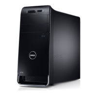
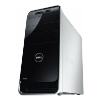
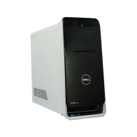
Identifies external components visible from the front of the computer.
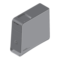
Identifies external components visible from the back of the computer.
Identifies internal components visible when the computer is open.
Details and labels various connectors and parts on the system board.
Step-by-step guide to safely detach the computer's outer casing for access.
Instructions for reattaching the computer's outer casing after maintenance.
Steps required before handling memory modules, including cover removal.
Procedure for safely detaching memory modules from their slots.
Procedure for installing new memory modules into the computer.
Steps to complete after memory module installation, including cover reinstallation.
Steps needed before removing or replacing the front bezel, like cover removal.
Guide to detach the front decorative panel of the computer.
Instructions for reattaching the front decorative panel of the computer.
Steps to take after front bezel replacement, including cover reinstallation.
Steps required before handling the graphics card bracket, such as cover removal.
Procedure to remove the bracket securing the graphics card.
Procedure to reinstall the bracket for the graphics card.
Final steps after bracket replacement, including cover reattachment.
Steps before graphics card removal/installation, including cover and bracket removal.
Procedure to safely detach the graphics card from the PCI-Express slot.
Procedure to install a new graphics card into the PCI-Express slot.
Steps after graphics card replacement, including bracket and cover reinstallation.
Steps required before handling PCI-Express x1 cards, including cover and bracket removal.
Procedure to safely detach PCI-Express x1 cards from their slots.
Procedure to install new PCI-Express x1 cards into their slots.
Steps after card replacement, including bracket and cover reinstallation.
Steps before handling the wireless Mini-Card, including cover removal.
Procedure to safely detach the wireless Mini-Card from its slot.
Procedure to install a new wireless Mini-Card into its slot.
Steps after Mini-Card replacement, including cover reinstallation.
Steps before antenna replacement, including cover, bezel, and top cover removal.
Procedure to detach antennas connected to the wireless Mini-Card.
Procedure to install new antennas for the wireless Mini-Card.
Steps after antenna replacement, including top cover, bezel, and main cover reinstallation.
Steps before mSATA drive handling, including cover removal.
Procedure to safely detach the mSATA drive from the system board.
Procedure to install a new mSATA drive onto the system board.
Steps after mSATA drive replacement, including cover reinstallation.
Instructions for removing and replacing the main hard disk drive.
Procedures for removing and replacing the physical cage that holds the hard drives.
Instructions for removing and replacing an optional secondary hard disk drive.
Instructions for removing and replacing the main optical drive.
Instructions for removing and installing an optional secondary optical drive.
Instructions for removing and replacing the media card reader module.
Instructions for removing and replacing the top panel of the computer.
Instructions for removing and replacing the top panel containing input/output ports.
Instructions for removing and replacing the front panel with USB ports.
Instructions for removing and replacing the computer's power button assembly.
Instructions for removing and replacing the main chassis cooling fan.
Instructions for removing and replacing the processor cooling assembly.
Procedures for safely removing and installing the computer's CPU.
Steps to complete after processor replacement, including fan/heat-sink and cover reinstallation.
Instructions for removing and replacing the CMOS coin-cell battery.
Instructions for removing and replacing the main power supply unit.
Instructions for removing and replacing the computer's motherboard.
Steps to input the computer's service tag into the BIOS settings.
Explains the purpose, access methods, and basic layout of the BIOS setup utility.
Details various configurable settings within the system setup utility, including hardware and security.
Options to define the order in which devices are checked for booting.
Procedure to reset BIOS passwords by manipulating jumpers.
Procedure to reset BIOS settings, including passwords, via jumper manipulation.
Steps to download and install updated BIOS firmware for the system.
Information on computer features and advanced options available.
| Tcase | 72.6 °C |
|---|---|
| Bus type | DMI |
| Stepping | D2 |
| Processor cache | 8 MB |
| Processor cores | 4 |
| Processor model | i7-2600 |
| System bus rate | 5 GT/s |
| Processor family | Intel® Core™ i7 |
| Processor series | Intel Core i7-2600 Desktop Series |
| Processor socket | LGA 1155 (Socket H2) |
| Processor threads | 8 |
| Processor codename | Sandy Bridge |
| Processor frequency | 3.4 GHz |
| Processor cache type | Smart Cache |
| Processor lithography | 32 nm |
| Processor manufacturer | Intel |
| Processor front side bus | - MHz |
| PCI Express slots version | 2.0 |
| Processor boost frequency | 3.8 GHz |
| Processor operating modes | 64-bit |
| ECC supported by processor | No |
| Thermal Design Power (TDP) | 95 W |
| Number of processors installed | 1 |
| CPU multiplier (bus/core ratio) | 34 |
| Maximum number of PCI Express lanes | 16 |
| Memory types supported by processor | DDR3-SDRAM |
| Memory clock speeds supported by processor | 1066, 1333 MHz |
| Memory bandwidth supported by processor (max) | 21 GB/s |
| Maximum internal memory supported by processor | 32 GB |
| Platform | PC |
| Power supply type | AC/DC |
| Compliance industry standards | IEEE 802.3, IEEE 802.3u, IEEE 802.3ab |
| Motherboard chipset | Intel® H77 Express |
| Memory slots | 4x DIMM |
| Internal memory | 8 GB |
| Memory channels | Dual-channel |
| Memory clock speed | 1600 MHz |
| Memory layout (slots x size) | 2 x 4 GB |
| HDD interface | SATA |
| Optical drive type | Blu-Ray DVD Combo |
| Card reader integrated | Yes |
| Total storage capacity | 2000 GB |
| On-board graphics card ID | 0x102 |
| On-board graphics card model | Intel® HD Graphics 2000 |
| On-board graphics card family | Intel® HD Graphics |
| On-board graphics card base frequency | 850 MHz |
| On-board graphics card dynamic frequency (max) | 1350 MHz |
| Number of displays supported (on-board graphics) | 2 |
| Display type | LED |
| Display diagonal | 18.5 \ |
| Display brightness | 250 cd/m² |
| Display resolution | 1366 x 768 pixels |
| Native aspect ratio | 16:9 |
| Viewing angle, vertical | 160 ° |
| Display number of colors | 16.78 million colors |
| Viewing angle, horizontal | 170 ° |
| Operating system installed | Windows 7 Home Premium |
| USB 2.0 ports quantity | 6 |
| Firewire (IEEE 1394) ports | 0 |
| Wi-Fi standards | 802.11b, 802.11g, Wi-Fi 4 (802.11n) |
| Cabling technology | 10/100/1000Base-T(X) |
| Top Wi-Fi standard | Wi-Fi 4 (802.11n) |
| Ethernet LAN data rates | 10, 100, 1000 Mbit/s |
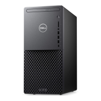
| Chassis type | Mini Tower |
| Product color | Black, Silver |
| Power supply | 460 W |
| Processor code | SR00B |
| Processor ARK ID | 52213 |
| Processor package size | 37.5 x 37.5 mm |
| Supported instruction sets | AVX |
| Intel Identity Protection Technology version | 1.00 |
| Depth | 445 mm |
|---|---|
| Width | 185 mm |
| Height | 406 mm |
| Weight | 12860 g |