Chapter 3 Connections and Wiring|ASDA-A&A+ Series
Revision April 2009 3-29
3.3.3 User-defined DI and DO signals
If the default DI and DO signals could not be able to fulfill users’ requirements, there are still user-
defined DI and DO signals. The setting method is easy and they are all defined via parameters. The
user-defined DI and DO signals are defined via parameters P2-10 to P2-17 and P2-18 to P2-22.
Please refer to the following Table 3.I for the settings.
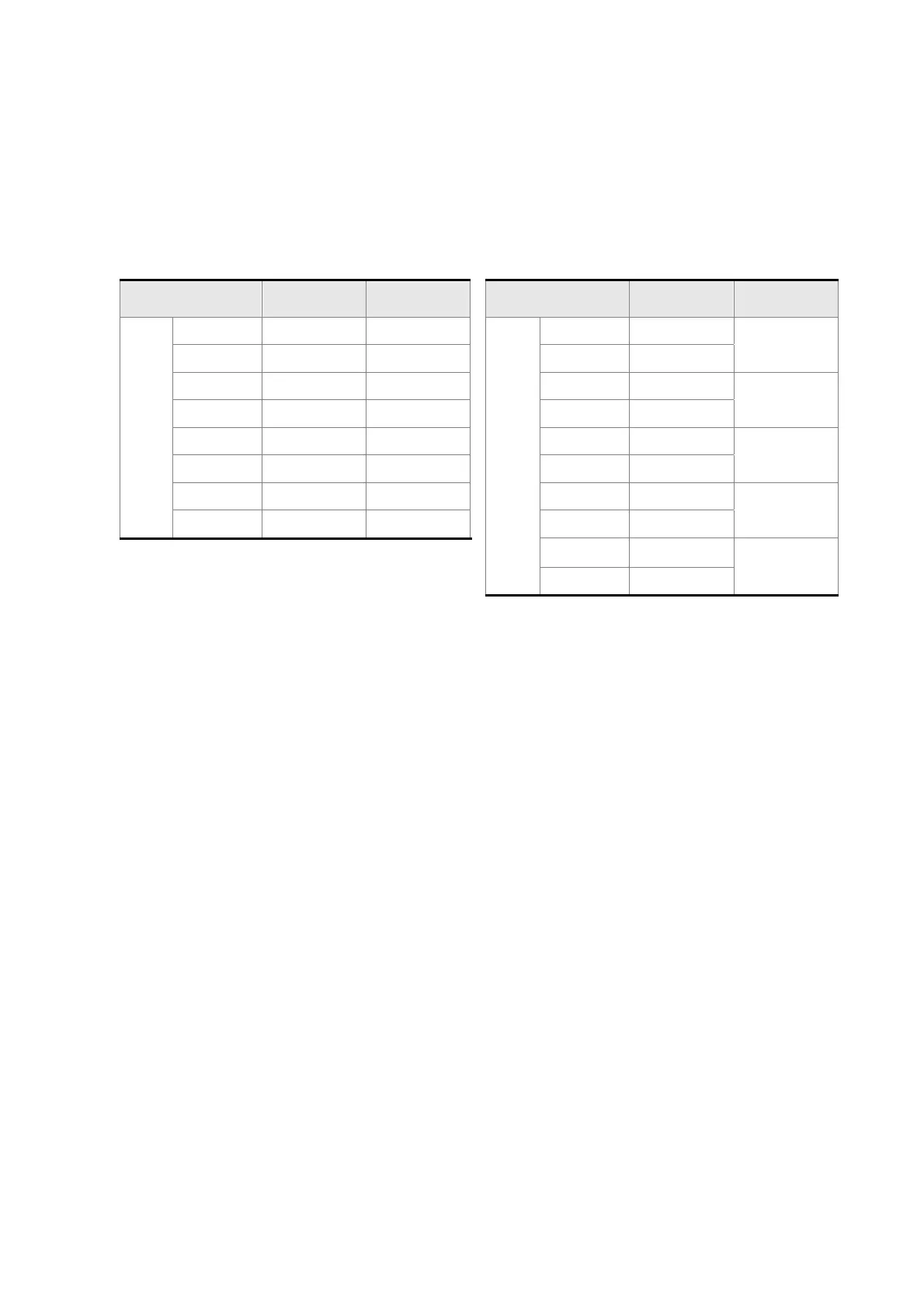
Table 3.I User-defined DI and DO signals
Signal Name Pin No. Parameter Signal Name Pin No. Parameter
DI1- 9 P2-10 DO1+ 7
DI2- 10 P2-11 DO1- 6
P2-18
DI3- 34 P2-12 DO2+ 5
DI4- 8 P2-13 DO2- 4
P2-19
DI5- 33 P2-14 DO3+ 3
DI6- 32 P2-15 DO3- 2
P2-20
DI7- 31 P2-16 DO4+ 1
DI
DI8- 30 P2-17 DO4- 26
P2-21
DO5+ 28
DO
DO5- 27
P2-22
DI signal:
For example: If the users want to set DI1 to be servo on, it only needs to set the value of parameter P2-
10 to 101 (refer to chapter 7).
DO signal:
For example: If the users want to set DO1 to be servo ready, it only needs to set the value of parameter
P2-18 to 101 (refer to chapter 7).
Call 1(800)985-6929 for Sales
Call 1(800)985-6929 for Sales