Do you have a question about the Delta Electronics ASD-A0221LA and is the answer not in the manual?
Information on how to use the manual and its contents.
Identifies the intended audience for the user manual.
Crucial safety instructions to follow before using the product.
Steps to verify the product upon receipt.
Explanation of model naming conventions for drives and motors.
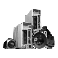
Details possible combinations of drives and motors.
Highlights key features of the ASDA-A series servo drive.
Explains the available single and dual modes of operation for the servo drive.
Important considerations and notes for installing the servo drive and motor.
Guidelines for storing the product properly to maintain warranty.
Specifies the recommended ambient temperature and environmental conditions for installation.
Guidelines for the correct installation procedure and required clearances.
Overview of connecting peripheral devices to the servo drive.
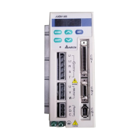
Detailed identification and description of servo drive connectors and terminals.
Description of the CN1 interface connector and its signal groups.
Wiring diagrams for I/O signals connected to CN1.
Overview of the digital keypad, its display panel, and function keys.
Illustrates the keypad operation and navigation flowchart.
Information on various status messages displayed by the drive.
Describes basic operations like fault display and JOG operation.
Steps for inspecting the drive and motor before trial run without load.
Steps to correctly apply power to the servo drive.
Steps to perform a JOG trial run without connecting any load.
Steps for performing a speed trial run without load.
Steps for performing a position trial run without load.
Procedure for estimating load inertia to servo motor inertia ratio using JOG mode.
Lists and describes the six single and five dual modes of operation for the servo drive.
Explains the position control mode, including command sources.
Explains the speed control mode (S or Sz).
Explains the Torque Control Mode (T or Tz).
Explains how to select between different control modes.
Covers miscellaneous functions like speed limit, torque limit, and regenerative resistors.
Defines parameter groups and abbreviations used in the manual.
Summarizes servo parameters by group.
Detailed listing of parameters by group (Monitor, Basic, Extension, Communication, Diagnosis).
Describes communication modes (RS-232, RS-485, RS-422) and connections.
Details communication addresses and transmission speed settings.
Explains MODBUS ASCII and RTU modes, data formats, and protocols.
Explains how to write and read communication parameters.
Steps for inspecting the drive and motor before operation.
Guidelines for proper product use, storage, and cleaning.
Information on the expected lifespan of key components like capacitors and relays.
Lists common servo drive and motor fault messages and their descriptions.
Provides potential causes and corrective actions for various fault messages.
Explains methods to clear detected faults by resetting or specific actions.
Detailed specifications for ASDA-A series servo drives across various power ratings.
Detailed specifications for ASDA-A+ series servo drives across various power ratings.
Technical specifications for low inertia ASMT□L series servo motors.
Technical specifications for medium inertia ASMT□M series servo motors.
Technical specifications for medium/high inertia ECMA series servo motors.
Explains overload protection functions and charts for load and operating time.
Provides dimensional drawings and weight for ASDA-A series servo drives.
Example of position control with homing function using limit switches and parameters.
Example application demonstrating roller feeding using position control.
Example of connecting the servo drive to a Delta DVP-EH Series PLC.
Example of connecting the servo drive to a Delta TP04 Series Operation Interface Panel.
Explains Position Control Mode (Pr Mode) with relevant parameters and timing charts.
Explains the Feed Step Control function and relevant parameters.
Explains the Internal Auto Running Mode with relevant parameters.
Details the Homing function, modes, parameters, and timing charts.
Lists Delta part numbers and specifications for power connectors.
Details Delta part numbers and lengths for power cables.
Lists Delta part numbers and specifications for encoder cables.
Details Delta part number for the CN1 I/O signal connector.
Shows combinations of servo drives, motors, cables, and connectors.
Specifications for built-in and external regenerative resistors.
Recommended values for circuit breakers and fuses for ASDA-A and ASDA-A+ series.
Cross-reference for recommended EMI filters for ASDA-A and ASDA-A+ series servo drives.
General precautions for EMI filter installation and wiring.
Precautions for selecting and installing motor cables for EMI filter performance.
| Brand | Delta Electronics |
|---|---|
| Model | ASD-A0221LA |
| Category | DC Drives |
| Language | English |