Do you have a question about the Delta Electronics ASD-A0421LA and is the answer not in the manual?
Verify product against order, check for damage, loose screws, and proper shaft rotation.
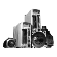
Details the naming conventions and structure of ASDA-A, ASDA-A+, ECMA series models.
Lists compatible servo drives and motors for ASDA-A and ASDA-A+ series.
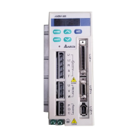
Describes the key features and components of the ASDA-A series servo drive.
Provides essential guidelines for installing the servo drive and motor to prevent damage.
Details operating temperature ranges and precautions for selecting a mounting location to avoid heat or dust issues.
Outlines correct mounting procedures and required clearances for ventilation and heat dissipation.
Explains how to connect peripheral devices to the servo drive, including wiring diagrams.
Identifies and describes the function of each terminal and connector on the servo drive.
Illustrates single-phase and three-phase power supply connection methods for servo drives.
Describes the CN1 connector, its terminal layout, and signal groups for I/O and control.
Explains the functions of the display panel and keys on the digital keypad.
Illustrates the keypad operation flow for navigating between monitor and parameter modes.
Covers operations like fault code display, JOG operation, and position learning.
Describes essential pre-run checks and safety precautions to prevent accidents and damage.
Explains how to perform a JOG trial run to test the servo drive and motor without any load.
Guides on performing a trial run in speed control mode without load, including necessary digital input settings.
Provides steps for estimating load inertia and tuning the servo drive for optimal performance.
Lists and describes the six single and five dual modes of operation supported by ASDA-A and ASDA-A+ series.
Details applications requiring precision positioning and the two command sources: external pulse train (Pt) and internal parameter (Pr).
Explains speed control applications using external analog or internal parameters, including S-curve and gain adjustment.
Describes how to select between multiple control modes like Pt-S, Pr-S, S-T, Pt-T, and Pr-T using digital inputs.
Defines parameter groups (Monitor, Basic, Extension, Communication, Diagnosis) and abbreviations.
Provides a summary of parameters listed by group (P0-xx, P1-xx, P2-xx, P3-xx, P4-xx).
Lists parameters within each group (Group 0: P0-xx, Group 1: P1-xx, etc.).
Explains the communication modes (RS-232, RS-485, RS-422) and connection configurations.
Details essential communication parameters like address and transmission speed for establishing communication.
Describes the ASCII and RTU modes, including data formats and code descriptions for MODBUS communication.
Covers essential checks before operation and general inspection points for the servo drive and motor.
Provides guidelines for periodic cleaning and maintenance of the servo drive and motor.
Lists display codes, fault names, and descriptions for servo drive errors.
Provides troubleshooting steps for common servo drive faults like overcurrent, overvoltage, and encoder errors.
Details electrical, mechanical, and environmental specifications for the ASDA-A series servo drives.
Provides detailed specifications for ASMTL series low inertia servo motors.
Shows dimensional drawings and weight for ASDA-A series servo drives of different power ratings.
Demonstrates a position control application with limit switches and homing, including parameter settings.
Guides on connecting Delta servo drives to DVP-EH series PLC for various functions like home, JOG, and position control.
Details relevant parameters and command registers for Pr mode position control.
Covers homing modes, sensor types, moving methods, and timing charts for enabling homing.
Lists Delta part numbers, housing, and terminal details for various power connectors.
Details part numbers, lengths (mm/inch), and straight plug types for power cables.
Lists part numbers and lengths for encoder cables, including straight plug specifications.
Provides recommended breaker and fuse values for ASDA-A and ASDA-A+ series servo drives.
Lists recommended EMI filters for ASDA-A and ASDA-A+ series servo drives based on power rating.
Offers general precautions for installing EMI filters and AC servo drives to ensure optimal performance.
| Model | ASD-A0421LA |
|---|---|
| Power | 0.4kW |
| Frequency Range | 50/60 Hz |
| Control Method | PWM (Pulse Width Modulation) |
| Control Mode | Speed, Torque |
| Cooling Method | Air Cooled |
| Protection Features | Overvoltage, Undervoltage, Overcurrent, Overload, Overtemperature |