Do you have a question about the Delta Electronics ASD-A1021MA and is the answer not in the manual?
Overview of manual structure, intended audience, and safety precautions.
Procedures for verifying the received product and checking for damage or loose screws.
Steps to verify the product received and ensure it matches the order.
Details on how to interpret model names and part numbers for drives and motors.
Table outlining compatible servo drive and motor models based on power rating.
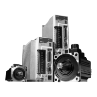
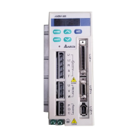
Description of the physical features and components of the ASDA-A series servo drive.
Explanation of available single and dual control modes for servo operations.
Guidelines for proper installation of servo drives and motors, including cable handling.
Recommendations for storing the product to maintain warranty and prevent damage.
Environmental and physical conditions required for installing servo drives and motors.
Step-by-step installation guidelines and required clearances for ventilation and heat dissipation.
Explains how to connect peripheral devices to the servo drive.
Diagrams and explanations for connecting various peripheral devices to the ASDA-A and ASDA-A+ series.
Detailed identification and description of servo drive connectors and their terminal functions.
Illustrates single-phase and three-phase power supply connection methods for servo drives.
Details on connector types and terminal assignments for motor power cables.
Specifications for encoder connectors, including terminal identification and wire colors.
Tables providing wire gauge and length specifications for power and encoder cables.
Overview of the digital keypad, display panel, and function keys on the servo drive.
Visual representation of the keypad operation and navigation within the servo drive's menu.
Explains various status messages shown on the LCD display after pressing SET key.
Details on performing common operations like Fault Code Display and JOG Operation.
Steps for inspecting the servo drive and motor before trial run to prevent damage and ensure safety.
Procedure for correctly connecting and turning on the power to the servo drive.
Steps for performing a JOG trial run to test the servo drive and motor without any load.
Procedure for conducting a speed trial run without load, including digital input settings.
Steps for performing a position trial run without load, detailing necessary DI signal settings.
Explains how to estimate load inertia and perform tuning using JOG mode and AutoMode.
Lists and describes the available single and dual control modes for ASDA-A and ASDA-A+ series servo drives.
Details on precision positioning applications, command sources, and loop gain adjustments.
Covers applications requiring precision speed control, command sources, and tuning modes.
Explains torque control applications, command sources, and smoothing strategies.
Describes how to select between different control modes using DI signals.
Covers additional functions like speed limit, torque limit, regenerative resistor, and electromagnetic brake.
Defines parameter groups and abbreviations for control modes.
Lists all parameters grouped by function and control mode applicability.
Describes the communication modes (RS-232, RS-485, RS-422) and connection configurations.
Details on setting communication addresses and transmission speeds for network connectivity.
Explains ASCII and RTU modes, data formats, and communication protocols.
Information on parameters for writing and reading communication settings.
Guidelines for general and pre-operation inspection of servo drives and motors.
Procedures for routine maintenance, cleaning, and conductor checks.
Information on the expected lifespan of components like smooth capacitors, relays, and cooling fans.
Lists display codes, fault names, and descriptions for servo drive and motor errors.
Identifies potential causes for faults and provides corresponding checking methods and corrective actions.
Methods for clearing various fault messages by resetting the drive or activating specific signals.
Technical specifications for ASDA-A series servo drives, including power, voltage, and performance characteristics.
Technical specifications for ASDA-A+ series servo drives covering electrical, environmental, and mechanical aspects.
Detailed specifications for low inertia servo motors, including power, torque, and dimensions.
Technical data for medium inertia servo motors, covering electrical, mechanical, and environmental parameters.
Specifications for ECMA series servo motors, including power, torque, inertia, and environmental ratings.
Graphical representation of servo motor performance across different inertia types.
Information on overload protection functions and charts detailing load and operating time.
Mechanical dimensions and mounting information for various ASDA-A series servo drives.
Mechanical dimensions for ASMT□L series low inertia servo motors.
Mechanical dimensions for ASMT□M series medium inertia servo motors.
Mechanical dimensions for ECMA series medium/high inertia servo motors.
Example of implementing position control with homing function using PLC digital inputs and outputs.
Example application of position control for a roller feeding mechanism with motor rotation logic.
Guide on connecting Delta servo drives to DVP-EH series PLC for various control functions.
Instructions for connecting servo drives to Delta TP04 Series Operation Interface Panel.
Detailed explanation of Pr mode, relevant parameters, and homing function modes.
Explanation of feed step control parameters and digital I/O signal settings.
Description of parameters and timing charts for internal auto-running modes.
Details on homing modes, relevant parameters, and timing charts for enabling homing.
Examples of connecting servo drives to external controllers like Delta DVP-EH PLC, TP04, and Mitsubishi FX series.
Lists Delta part numbers and specifications for power connectors.
Details on Delta part numbers and lengths for power cables.
Lists Delta part numbers for encoder cables with specifications.
Identifies the Delta part number for the CN1 I/O signal connector.
Tables showing combinations of servo drives, motors, cables, and connectors.
Specifications for built-in and external regenerative resistors for ASDA-A and ASDA-A+ series.
Recommended breaker and fuse values for ASDA-A and ASDA-A+ series servo drives.
Cross-reference for recommended EMI filters for ASDA-A and ASDA-A+ series servo drives.
Guidelines for installing EMI filters to minimize noise and interference.
General precautions for achieving optimal EMI filter performance and installation.
Advice on selecting motor cables and precautions for proper installation affecting EMI filter performance.
Mechanical dimensions for specific EMI filter models.
| Brand | Delta Electronics |
|---|---|
| Model | ASD-A1021MA |
| Category | DC Drives |
| Language | English |