Chapter 3 Connections and Wiring|ASDA-A&A+ Series
3-32 Revision April 2009
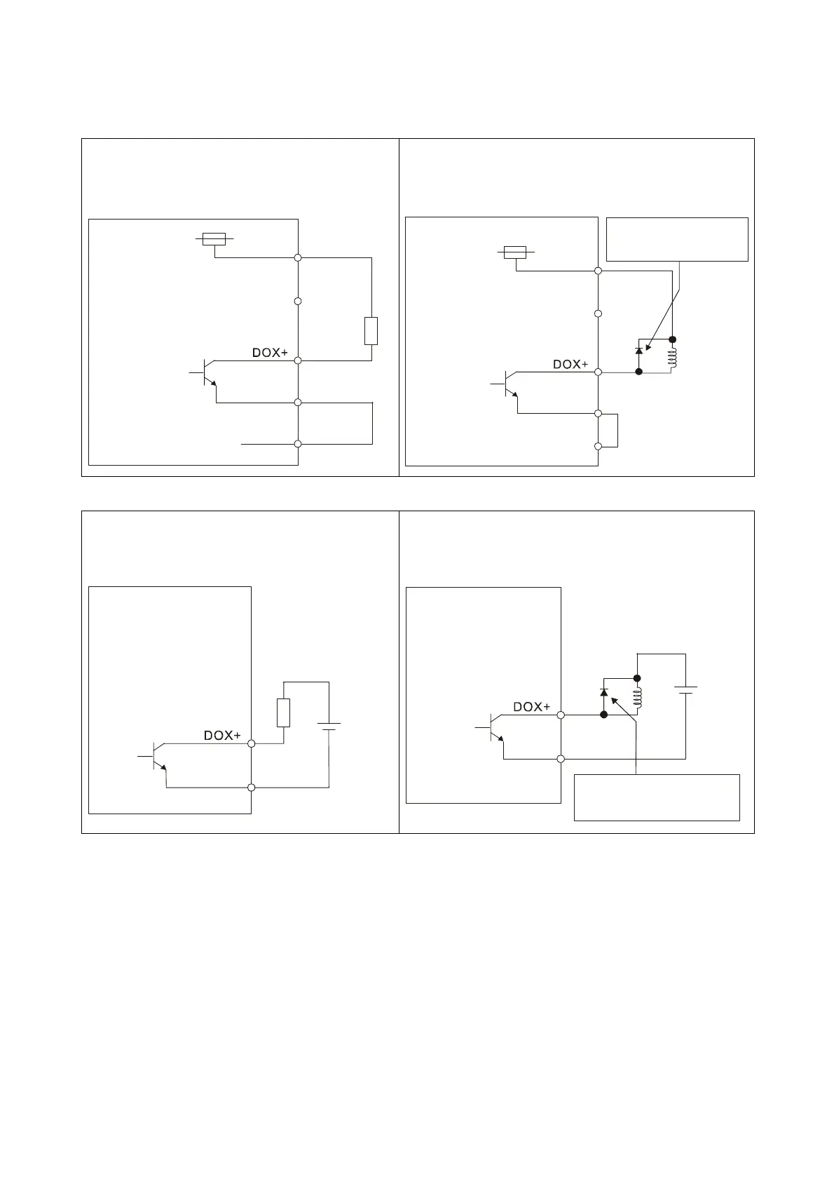
Be sure to connect a diode when the drive is applied to inductive load.
(Continuous maximum current: 40mA, Instantaneous peak current: max. 100mA)
C5: Wiring of DO signal, for the use of internal
power supply, general load
C6: Wiring of DO signal, for the use of internal power
supply, inductive load
VDD
DC24V
DOX-
COM-
R
Servo Drive
DOX: (DOX+, DOX-)
DO1: ( 7, 6)
X=1,2,3,4,5
DO2: ( 5, 4)
DO3: ( 3, 2)
DO4: ( 1, 26)
DO5: (28, 27)
17
45
VDD
DC24V
DOX-
COM-
Servo Drive
Ensure the polarity(+,-)
of Diode is correct or it
may damage the drive.
DOX: (DOX+, DOX-)
DO1: ( 7, 6)
X=1,2,3,4,5
DO2: ( 5, 4)
DO3: ( 3, 2)
DO4: ( 1, 26)
DO5: (28, 27)
17
45
C7: Wiring of DO signal, for the use of external
power supply, general load
C8: Wiring of DO signal, for the use of external power
supply, inductive load
DC24V
DOX-
R
Do not connect
VDD-COM+
DC24V
50mA
Servo Drive
DOX: (DOX+, DOX-)
DO1: ( 7, 6)
X=1,2,3,4,5
DO2: ( 5, 4)
DO3: ( 3, 2)
DO4: ( 1, 26)
DO5: (28, 27)
X=1,2,3,4,5
DOX-
DC24V
Do not connect
VDD-COM+
Servo Drive
Ensure the polarity (+, -)
of the Diode is correct or
it may damage the drive.
DOX: (DOX+, DOX-)
DO1: ( 7, 6)
X=1,2,3,4,5
DO2: ( 5, 4)
DO3: ( 3, 2)
DO4: ( 1, 26)
DO5: (28, 27)
Call 1(800)985-6929 for Sales
Call 1(800)985-6929 for Sales