Chapter 3 Connections and Wiring|ASDA-A&A+ Series
3-30 Revision April 2009
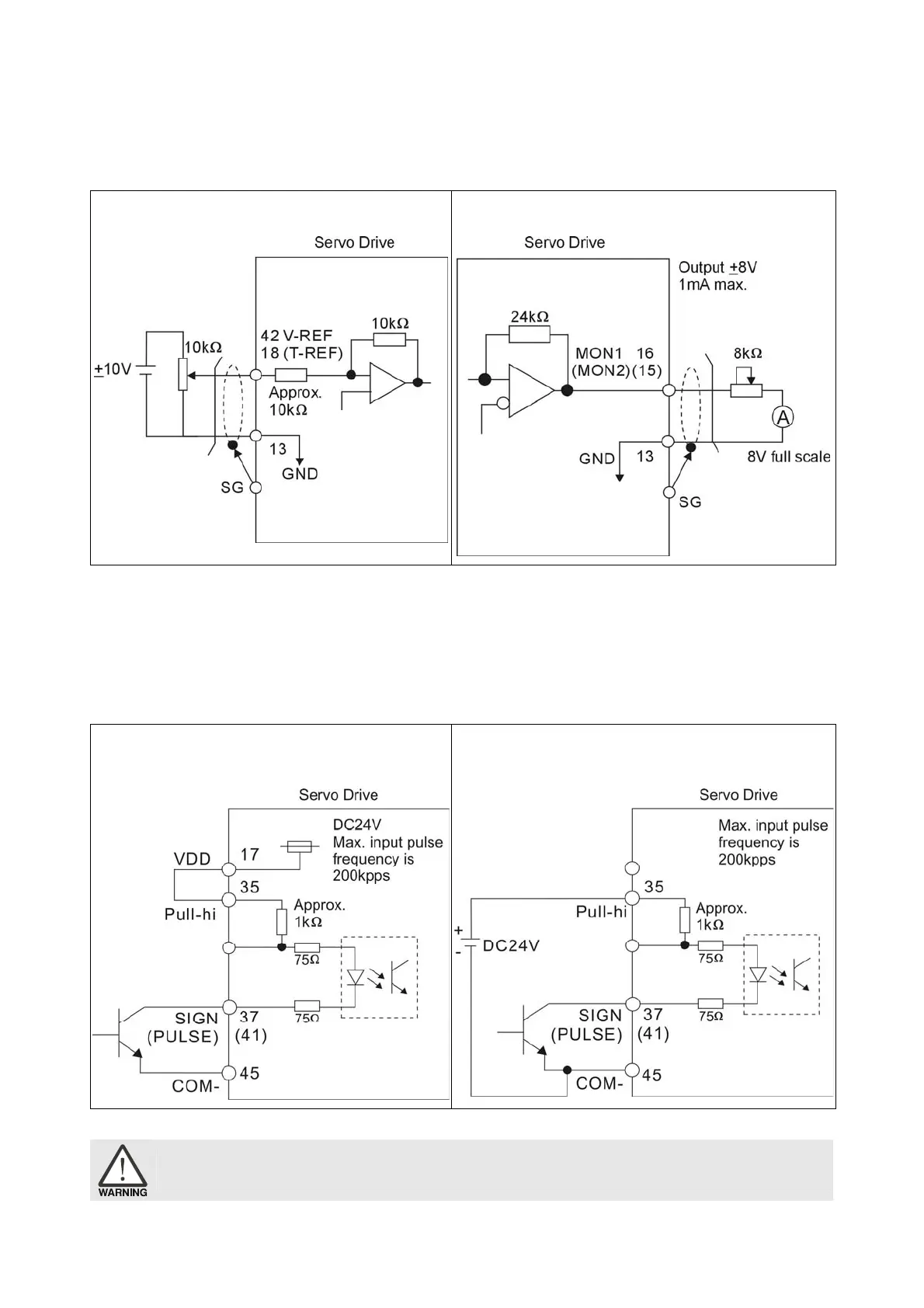
3.3.4 Wiring Diagrams of I/O Signals (CN1)
The valid voltage range of analog input command in speed and torque mode is -10V ~+10V. The
command value can be set via relevant parameters.
C1: Speed / Torque analog signal input C2: Analog monitor output (MON1, MON2)
There are two kinds of pulse inputs, Line driver input and Open-collector input. Max. input pulse
frequency of Line driver input is 500kpps and max. input pulse frequency of Open-collector input is
200kpps.
C3-1: Pulse input, for the use of internal power
supply (Open-collector input)
C3-2: Pulse input, for the use of external power
supply (Open-collector input)
¾ Caution: Do not use dual power supply. Failure to observe this caution may result in damage to the servo drive
and servo motor.
Call 1(800)985-6929 for Sales
Call 1(800)985-6929 for Sales