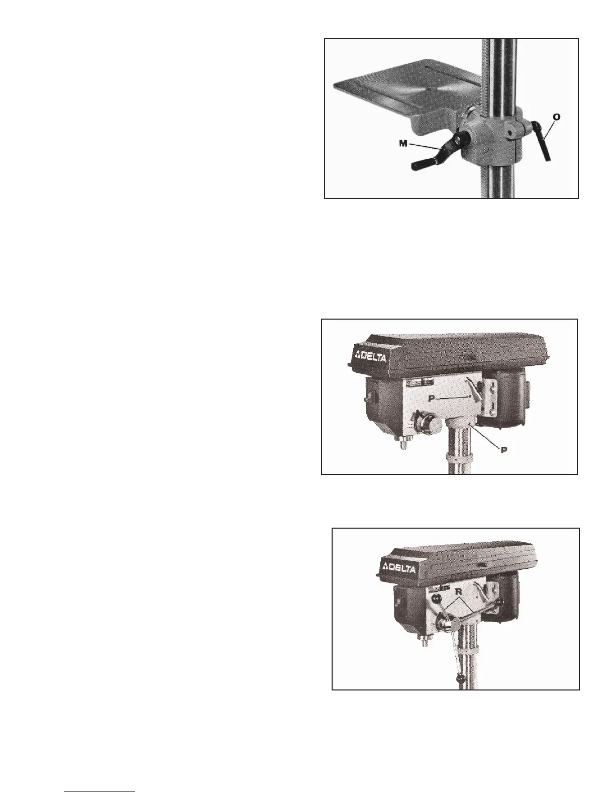
7. Assemble table raising and lowering handle (M) Fig.
8, to shaft on table bracket and tighten set screw in han-
dle against flat on shaft.
8. Thread table bracket lock screw (O) Fig. 8, into hole
in table bracket, as shown.
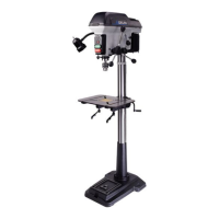
9. Place the drill press head onto the column as far
as it will go. After the drill press spindle is aligned with
the table and base, tighten the two set screws (P) Fig.
9.
10. Thread the three pinion shaft handles (R) Fig. 10,
into the three tapped holes located in the pinion shaft
hub,as shown.
Fig. 8
Fig. 9
Fig. 10