6
ASSEMBLY
ATTACHING BELT
SANDER TABLE
1. DISCONNECT MACHINE FROM POWER SOURCE.
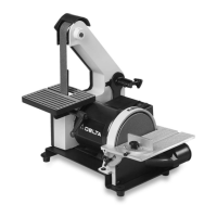
2. Locate the 1-3/16" long screw (A) Fig. 2, M8.4 flat
washer (B), and table locking handle assembly (C), (D),
(E) and (F). NOTE: The table locking assembly (C, D, E,
and F) is shipped assembled. For ease in assembling
table to sander, remove screw and spring (E) and (F), and
handle (D) from locking stud (C).
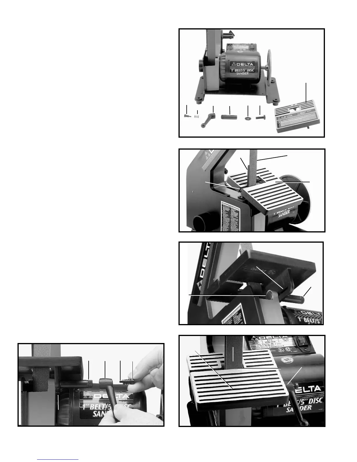
3. Place table (G) Fig. 3, on sander by inserting belt (H)
and platen (I) through opening (J) in table, as shown.
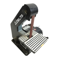
4. Insert 1-3/16" long screw (A) Fig. 4, into hole in
sander frame and through slot (K) underneath table and
fasten using M8.4 flat washer and stud (C), tighten the
stud (C) by hand.
5. The M8.4 flat washer (B) and stud (C) are also shown
in Fig. 5. Place handle (D) on end of stud and fasten in
place using spring (E) and screw (F) Fig. 5.
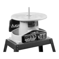
6. The table (A) is shown completely assembled to the
sander in Fig. 6. NOTE: The locking handle (B) is spring
loaded and can be repositioned by pulling out the handle
and repositioning it on the serrations located underneath
the handle. WARNING: To avoid trapping the
workpiece or your fingers between the table (A) and
the sanding belt (D), adjust the table so that it is a
maximum 1/16" from belt, between the work table
and the belt (see the section “BELT TABLE
ADJUSTMENTS”).
Fig. 2
A
B
C
D
E
F
G
Fig. 3
G
H
I
J
Fig. 4
A
K
C
Fig. 5
B
C
D
E
F
Fig. 6
A
B
C
D