Do you have a question about the Delta 31-460 and is the answer not in the manual?
Covers safe tool use, maintenance, and avoiding hazards like forcing the tool or overreaching.
Emphasizes eye protection, proper attire, clean workspace, and keeping others away.
Details risks associated with dust and chemicals from certain materials.
Guidelines for proper belt tracking, workpiece support, and sanding techniques.
Covers assembly, material limitations, cleaning, and warnings about accessories.
Details on circuit, fuse, and extension cord requirements for safe operation.
Information on the sander's motor voltage and frequency.
Explains the necessity of grounding, how to connect, and adapter usage.
Guidance on choosing appropriate gauge and length extension cords.
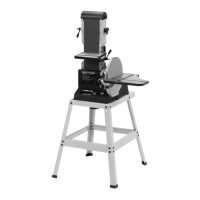
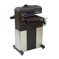
Introduction to the Delta Model 31-460 sander and its features.
Steps for unpacking the machine and removing protective coatings.
Procedure for setting the correct tension on the sanding belt.
Instructions for attaching the belt and pulley guard to the machine base.
Steps to install the sanding disc plate onto the drive shaft.
Procedure for securing the lower cover using sheet metal screws.
Steps to install and secure the rod for the disc sander table.
Guidance on mounting the table and ensuring proper clearance.
Instructions for fastening the dust spout to the sander base.
Procedure for attaching the backstop to the sanding arm.
Methods for securely mounting the sander to a stable surface.
Specifications for a mounting board and hole placement.
How to operate the power switch to turn the sander on and off.
Method to prevent unauthorized use by removing the switch toggle.
Instructions for adjusting the tracking knob to align the belt.
How to position the sanding arm horizontally, vertically, or at an angle.
Procedure to ensure the sanding arm is level with the workbench.
How to check and adjust the backstop for square alignment with the belt.
Steps to tilt the table and reposition it for proper clearance.
How to adjust the table to be 90 degrees to the sanding disc.
Procedure to check and adjust the miter gage slot parallel to the disc.
How to use the miter gage for angled sanding and adjust its tilt.
Steps to detach the table assembly from the disc unit and attach to the belt unit.
Information on connecting the dust spout to a shop vacuum hose.
Location for storing the two wrenches supplied with the sander.
Step-by-step guide to removing and installing a new sanding belt.
Steps for removing the old disc and applying the new one.
Techniques for surfacing and edge sanding using the belt in horizontal position.
How to sand inside curves using the top sanding drum of the belt.
Technique for sanding outside curves on the sanding disc, with safety notes.
Using the belt for end sanding wide pieces, including miter gage use.
Using the disc for end sanding narrow pieces with the miter gage.
Information on Delta accessories and warnings about using non-Delta parts.
Provides contact numbers for parts, service, and warranty assistance.
Summary of the product's limited warranty coverage and terms.
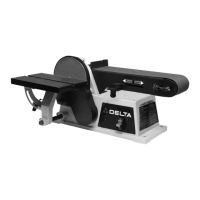
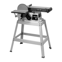
The Delta 4" Belt / 6" Disc Sander (Model 31-460) is a versatile woodworking machine designed for sanding various wood and wood-like products. It features both a belt and a disc sanding unit, allowing for a wide range of sanding applications, from surfacing and edge sanding to working on curves and end grains. The machine is equipped with a single-phase induction motor, providing reliable power for consistent performance.
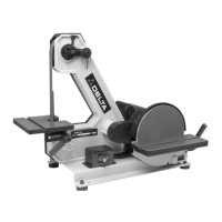
One of the key features of this sander is its adjustable sanding arm. The sanding arm can be positioned horizontally, vertically, or at any angle in between, offering flexibility for different workpiece shapes and sizes. This adjustability is achieved by loosening a screw, setting the arm to the desired angle, and then tightening the screw to secure it in place. A positive stop is also provided to ensure the sanding arm is level with the workbench when in the horizontal position, which can be adjusted for precise alignment.
The machine includes a tilting aluminum table that can be mounted for use with either the belt or the disc unit. This table can be tilted up to 45 degrees to the right, enabling angled sanding operations. To adjust the table angle, the table lock knob is loosened, the table is tilted, and then the knob is tightened. It's crucial to reposition the table assembly on its support rod after tilting to maintain a maximum clearance of 1/16 inch between the sanding disc and the table edge. This prevents trapping the workpiece or fingers, ensuring safe operation. The table's squareness with the sanding disc can also be adjusted using a combination square, and a pointer allows for precise alignment with the angle scale.
For sanding with the belt unit, a backstop is provided. This backstop is essential for preventing the workpiece from being carried along the belt, especially during surfacing or edge sanding. The backstop's edge must be positioned a maximum of 1/16 inch away from the sanding belt to avoid trapping the workpiece or fingers. The backstop's squareness with the sanding belt can be checked and adjusted by loosening a screw. Inside curves can be sanded on the top sanding drum of the belt unit, offering specialized functionality for curved work.
When using the disc unit, the miter gage, supplied as a standard accessory, is used with the disc table. The miter gage body can be tilted right or left for angle or miter sanding by loosening and tightening its lock knob. For end sanding of narrow workpieces, the sanding disc and miter gage are utilized, with the workpiece moved from the center to the left side of the disc. It's critical to always sand on the left (downward) side of the sanding disc, as sanding on the right (upward) side could cause the workpiece to fly up, posing a hazard. Similar to the belt unit, the table edge must be positioned a maximum of 1/16 inch away from the sanding disc to prevent trapping.
Maintenance features include straightforward procedures for replacing both the sanding belt and the sanding disc. To replace the sanding belt, the machine must be disconnected from the power source, the backstop removed, and the belt tension lever slid to release tension. The old belt is then removed, and a new one is slid over the sanding drums, ensuring it runs in the direction of the arrow located on the inside of the belt. Tension is then reapplied, the backstop replaced, and the belt tracking checked and adjusted if necessary using the tracking knob.
Replacing the sanding disc also requires disconnecting the machine from the power source. The table assembly is loosened and removed, followed by the removal of screws holding the lower cover. The old disc is peeled off, and a new one is pressed firmly into position on the disc plate. The lower cover and table assembly are then reinstalled.
The sander is designed for indoor use and should be mounted on horizontal surfaces only to prevent motor damage. For permanent installation, it can be securely fastened to a firm supporting surface like a stand or workbench using four holes in the base. An alternative method involves fastening the sander to a mounting board, which is then clamped to a stand or workbench.
A dust spout is included for connecting to a standard shop vacuum hose, facilitating proper dust removal and maintaining a clean work area. This is important as dust generated by woodworking can be injurious to health. The machine also features convenient storage holes in the base casting for the two wrenches supplied with the sander.
Safety is a paramount consideration, with numerous warnings and instructions provided throughout the manual. These include wearing eye protection, keeping guards in place, securing workpieces, and avoiding awkward hand positions. The switch can be locked in the "OFF" position to prevent unauthorized use by removing the switch toggle. Grounding instructions are detailed to protect the operator from electric shock, emphasizing the use of 3-wire extension cords with proper grounding. The manual also highlights the importance of using recommended accessories and avoiding solvents for cleaning plastic parts.
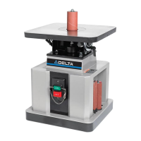
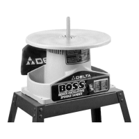
| Type | Oscillating Spindle Sander |
|---|---|
| Speed | 1725 RPM |
| Table Tilt | 0 - 45 degrees |
| Spindle Sizes Included | 1/2, 1, 1 1/2, 2 inches |
| Dust Port | 2-1/4 inches |