11
OPERATING CONTROLS
AND ADJUSTMENTS
Fig. 24
Fig. 23
Fig. 22
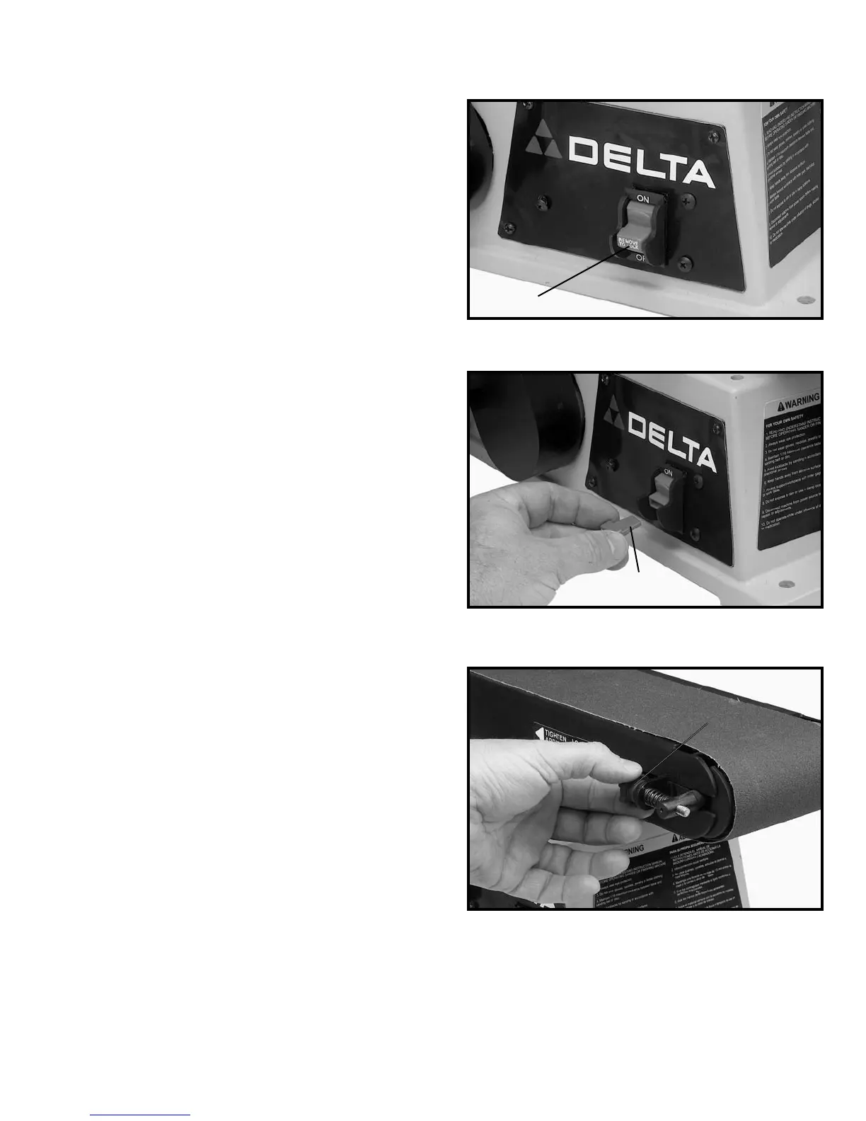
STARTING AND
STOPPING SANDER
The switch (A) Fig. 22, is located on the sander base.
To turn the sander “ON” move the switch to the up
position. To turn the sander “OFF” move the switch to
the down position.
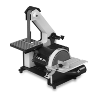
LOCKING SWITCH IN
THE “OFF” POSITION
IMPORTANT: When the machine is not in use, the switch
should be locked in the “OFF” position to prevent
unauthorized use. This can be done by grasping the
switch toggle (B) Fig. 23, and pulling it out of the switch
as shown. With the switch toggle (B) removed, the switch
will not operate. However, should the switch toggle be
removed while the machine is running, it can be turned
“OFF” once, but cannot be restarted without inserting
the switch toggle (B).
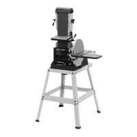
TRACKING THE
SANDING BELT
1. Turn the switch “ON” and “OFF” and check to see
if the sanding belt tends to move to one side or the
other on the two sanding drums. If the belt does not
move to one side or the other and rides on the center
of the sanding drums the belt is tracking properly.
2. If the sanding belt moves toward the disc, turn the
tracking knob (A) Fig. 24, counterclockwise 1/4 turn.
3. If the sanding belt moves away from the disc, turn
the tracking knob (A) Fig. 24, clockwise 1/4 turn.
4. Turn the switch “ON” and “OFF” again, and check
to see if the sanding belt moves to one side or the other
and readjust tracking knob if necessary.
A
B
A