EasyManua.ls Logo

Delta 31-280 User Manual

Delta 31-280
16 pages
To Next Page IconTo Next Page
Page #1 background imageLoading...
Page #1 background image
INSTRUCTION MANUAL
Sanding Center
6" Belt/12" Disc Sander
(Model 31-280)
PART NO. 406-12-651-0004 - 07-31-01)
Copyright © 2001 Delta Machinery
To learn more about DELTA MACHINERY
visit our website at: www.deltamachinery.com.
For Parts, Service, Warranty or other Assistance,
please call
1-800-223-7278 (In Canada call 1-800-463-3582).
Question and Answer IconNeed help?

Do you have a question about the Delta 31-280 and is the answer not in the manual?

Delta 31-280 Specifications

General IconGeneral
TypeOscillating Spindle Sander
Motor Power1/2 HP
Dust CollectionYes
Table Tilt0-45 degrees
Spindle Speed1725 RPM
Oscillation Stroke1 inch
Spindle Sizes Included1/2", 1-1/2", 2"

Summary

GENERAL SAFETY RULES

General Safety Precautions

Comprehensive safety guidelines for operating woodworking machinery, covering personal protection, work area, and tool handling.

ADDITIONAL SAFETY RULES FOR SANDING CENTER

Sanding Center Specific Safety Rules

Specific safety instructions for the sanding center, including operation, belt/disc checks, and material handling.

POWER CONNECTIONS

MOTOR SPECIFICATIONS

GROUNDING INSTRUCTIONS

Grounding Procedures and Requirements

Detailed instructions on proper grounding for electrical safety, including cord types and outlet requirements.

EXTENSION CORDS

Extension Cord Gauge Recommendations

Guidelines for selecting the correct gauge and type of extension cord based on amperage rating, voltage, and cord length.

CHANGING VOLTAGE

Procedure for Converting Motor to 240 Volts

Step-by-step instructions to reconfigure the motor from 120V to 240V operation, including wiring and plug changes.

OPERATING INSTRUCTIONS

Unpacking and Cleaning

Instructions for carefully unpacking the tool, removing protective coatings, and cleaning unpainted surfaces.

ASSEMBLY INSTRUCTIONS

Assembling Stand

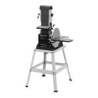
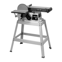
Steps for assembling the stand for the sanding center, including attaching legs, braces, and feet.

Attaching Tool to Stand

Attaching Sanding Disc

Attaching Disc Table

Attaching Dust Chute

Moving Sanding Arm to the Vertical Position

OPERATING CONTROLS AND ADJUSTMENTS

Starting and Stopping the Tool

How to operate the on-off switch to start and stop the sanding center.

Locking Switch in the "OFF" Position

Important safety step to prevent unauthorized use by locking the switch in the off position with a padlock.
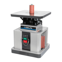
OVERLOAD PROTECTION

ADJUSTING TENSION AND TRACKING OF THE SANDING BELT

ADJUSTING SANDING BELT TABLE 90 DEGREES TO BELT

TILTING THE BELT SANDER TABLE

ADJUSTING BELT SANDER TABLE MITER GAUGE SLOT PARALLEL TO SANDING BELT

CHANGING POSITION OF SANDING ARM

ADJUSTING SANDING DISC TABLE 90 DEGREES TO DISC

TILTING THE DISC SANDER TABLE

ADJUSTING DISC TABLE MITER GAUGE SLOT PARALLEL TO SANDING DISC

ADJUSTING SANDING DISC GUARD

ACCESSORY HOLDER

CIRCLE SANDING ATTACHMENT

POWER TAKE-OFF SHAFT

REPLACING SANDING BELT

REPLACING SANDING DISC

ACCESSORIES

PARTS, SERVICE OR WARRANTY ASSISTANCE

Two Year Limited Warranty

PORTER-CABLE • DELTA SERVICE CENTERS

CANADIAN PORTER-CABLE • DELTA SERVICE CENTERS

Related product manuals