9
Fig. 15
Fig. 16
Fig. 14
Fig. 13
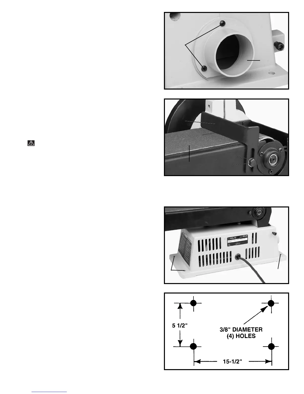
ASSEMBLING DUST SPOUT
1. Fasten dust spout (A) Fig. 13, to sander base using
the three 3/8" (10mm) long pan head screws, two of
which are shown at (B), and flat washers supplied.
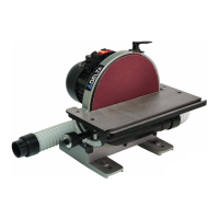
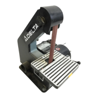
ASSEMBLING BACKSTOP
TO SANDING ARM
1. Assemble backstop (A) Fig. 14, to the sanding arm
using the 1/2" long hex head screw (B) and 5/16" flat
washer (C). Do not overtighten screw (B).
WARNING: TO AVOID TRAPPING THE WORK OR
FINGERS BETWEEN THE BACKSTOP AND SANDING
BELT, THE EDGE (D) OF THE BACKSTOP SHOULD BE
POSITIONED A MAXIMUM OF 1/16 INCH AWAY
FROM SANDING BELT (E).
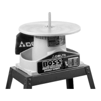
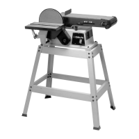
FASTENING SANDER TO SUPPORTING SURFACE
1. If your sander is to be used in a permanent location,
it should be fastened securely to a firm supporting
surface, such as a stand or workbench using the four
holes, three of which are shown at (A) Fig. 15.
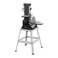
2. The diagram, shown in Fig. 16, illustrates the size
and center to center distance of the holes to be drilled in
the stand or workbench.
A
B
B
C
E
D
A
A
A