This document is an instruction manual for the Platinum Edition 2-Speed Heavy-Duty Wood Shaper (Model 43-424), manufactured by Delta Machinery. It covers safety rules, assembly instructions, operating controls and adjustments, and available accessories.
Function Description
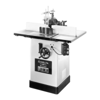
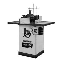
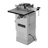
The Delta Model 43-424 is a heavy-duty wood shaper designed for various woodworking operations, primarily shaping wood with cutters. It features a two-speed motor, allowing for versatile applications depending on the type of cut and material. The shaper is equipped with a fence system, guards, and a spindle raising and lowering mechanism for precise control over the cutting process. It is intended for both straight and curved shaping, utilizing a fence, miter gauge, starting pin, and rub collars as guides.
Important Technical Specifications
- Model: 43-424 (Platinum Edition 2-Speed Heavy-Duty Wood Shaper)
- Motor: Single phase, 3 horsepower. Designed for 220-240 volt power systems.
- Spindle Speeds: Two speeds: 7,000 R.P.M. and 10,000 R.P.M., achieved by adjusting the belt position on a 2-step motor pulley and a 2-step spindle pulley.
- Spindle Travel Range: 0 to 3 inches, marked in 1/16-inch increments.
- Table Inserts: Three different sized table inserts are provided, with the large insert being adjustable for flush setting.
- Spindle Guard: 4-1/2 inch diameter, supplied with a 1/2-inch bushing for use with both 1/2-inch and 3/4-inch spindles. The guard diameter should be at least 1 inch more than the maximum cutting circle of the shaper cutter, and its height should not exceed 1/4 inch above the material.
- Extension Wings: Two 10-inch wide cast iron extension wings are included to expand the work surface.
- Cutter Hole: 1/2 inch spindle hole for high-speed steel 3-lip shaper cutters.
- Bore Sizes for Accessories: Cutters and collars are available for 1/2", 3/4", and 1" bore sizes.
- Power Connection: Three-prong plug for grounding. Requires a 220-240 volt, single-phase electrical outlet with proper grounding. Extension cords should be appropriately sized (e.g., 14 AWG for 50 ft, 12 AWG for 100 ft).
Usage Features
- Spindle Raising and Lowering: Controlled by a handwheel and lock knob, allowing for precise cutter height adjustments.
- Speed Change: Manual adjustment of the drive belt between two pulleys to select either 7,000 or 10,000 R.P.M. A chart inside the motor access door indicates correct belt placement.
- Spindle Rotation Reversal: The motor is equipped with a reversing switch, located on the motor junction box, to change the direction of spindle rotation. This should only be done when the motor is off.
- Fence System:
- Can be mounted parallel or 90 degrees to the miter gauge slot.
- Fence halves are adjustable endwise to control the opening at the spindle, ensuring it's never more than required to clear the cutter.
- Each fence half can be moved independently forward or backward using adjusting knobs and lock knobs.
- Indicator collars are provided for precise fence adjustments.
- Shims can be used to ensure fence halves are parallel.
- Guarding System:
- Includes a spring clamp, holddown, and clear plastic guard, all fully adjustable for various applications.
- The guard assembly can be flipped up and locked out of the way when not in use or during adjustments.
- A spindle guard is provided for additional safety during shaping operations.
- Shaping Methods:
- Using the Fence as a Guide: Recommended for straight work. The fence can be adjusted for average cuts (front and rear fences in a straight line) or for operations removing the entire edge (rear fence advanced to contact the work after the initial cut).
- Using Collars and Starting Pin: For curved shaping. Requires smooth collars and work edges. A portion of the work edge must remain untouched by cutters to provide sufficient bearing surface against the collar. The starting pin provides initial support before the work engages the collar. Collars can be positioned above, below, or between cutters, each offering different advantages for visibility and preventing gouging.
- Accessories: A wide range of Delta shaper cutters (high-speed steel, 3-lip), spacing collars, ball bearing rub collars, T-bushings, and specialized jigs (Sliding Shaper Jig, Auto-Set® Miter Gage) are available for various shaping profiles and operations. A mobile base is also available for portability.
Maintenance Features
- Cleaning: The manual provides instructions for unpacking and cleaning the shaper, including removing protective coating from machined surfaces with kerosene.
- Tool Condition: Emphasizes keeping tools sharp and clean for best and safest performance.
- Lubrication: Instructions for lubricating and changing accessories are mentioned as part of general maintenance.
- Part Replacement: In case of missing, damaged, or failed parts, the manual advises shutting off the switch, removing the plug, and replacing parts before resuming operation.
- Belt Tension Adjustment: Instructions are provided for checking and adjusting belt tension (approximately 3/32" deflection with light finger pressure) to ensure maximum belt performance and reduce wear.
- Pulley Alignment: Instructions for checking and aligning spindle and motor pulleys are included to optimize belt performance and longevity.
- Spindle Cartridge Replacement: Specific instructions are given for replacing the spindle cartridge, including torque specifications for the bolt.
- Safety Equipment: The manual stresses the importance of keeping guards in place and in working order, and regularly checking for damaged parts.