2. Programming Concepts
3. When the power of PLC goes from “OFF” to “ON”, the content of D1020 is set to 10
automatically.
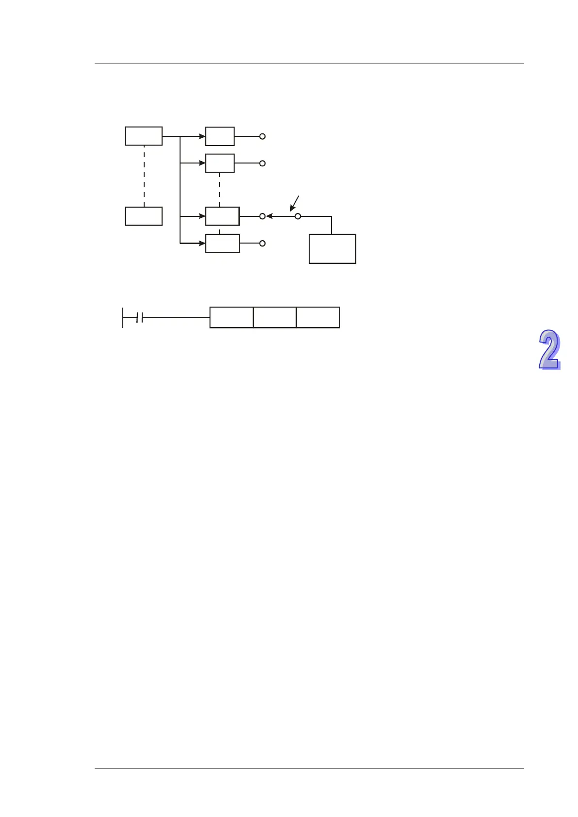
X0
X7
0ms
1ms
10ms
15ms
0
1
10
15
Terminal
response time
Status
memory
Update input
status
Set by D1020
(default: 10)
4. If the following programs are executed, the response time of X0 ~ X7 will be set to 0ms.
However, the fastest response time of input terminals will be 50μs due to that all terminals are
connected with RC filters..
M1000
MOV K0 D1020
normally ON contact
5. It is not necessary to adjust response time when using high-speed counters or interrupts
6. Using API 51 REFF instruction has the same effect as modifying D1020 and D1021.
X6 pulse width detecting function
Contents:
When M1084 = ON, X6 pulse width detecting function is enabled and the detected pulse width is
stored in D1023 (unit: 0.1ms)
M1083 On:detecting width of negative half cycle (OFFON)
M1083 Off:detecting width of positive half cycle (ONOFF)
Contents:
In the connection between PLC and PC/HMI, M1025 will be ON when PLC receives illegal
communication request during the data transmission process. The error code will be stored in
D1025.
01: illegal instruction code
02: illegal device address.
03: requested data exceeds the range.
07: checksum error
Pulse output Mark and Mask function
Number
M1108, M1110, M1156, M1157, M1158, M1538, M1159, M1540, D1026,
D1027, D1135, D1136, D1232, D1233, D1234, D1235, D1348, D1349
Contents:
Please refer to explanations of API 59 PLSR / API 158 DDRVI / API 197 DCLLM instructions.
M1029, M1030, M1102, M1103
Contents:
Execution Completed Flag:
MTR, HKY, DSW, SEGL, PR:
M1029 = ON for a scan cycle whenever the above instructions complete the execution.
PLSY, PLSR: