ASDA-A2 Chapter 6 Control Mode of Operation
Revision February, 2017 6-33
Relevant description of semi-auto mode setting:
1. When the system inertia is stable, the value of P2-33 will be 1 and
the system stops estimating. The inertia value will be saved to P1-
37 automatically. When switching mode to semi-auto mode (from
manual or auto mode), the system starts to estimate again.
2. When the system inertia is over the range, the value of P2-33 will
be 0 and the system starts to estimate and adjust again.
Manual Mode
When P2-32 is set to 0, users can define Speed Loop Gain (P2-04), Speed Integral Compensation
(P2-06) and Speed Feed Forward Gain (P2-07). Influence of each parameter is as the followings.
Proportional gain: To increase proportional gain can enhance the response frequency of speed
loop.
Integral gain: To increase the integral gain could increase the low-frequency stiffness of speed loop,
reduce the steady-state error and sacrifice the phase margin. The over high integral gain will cause
the instability of the system.
Feed forward gain: Diminish the deviation of phase delay.
Relevant parameters:
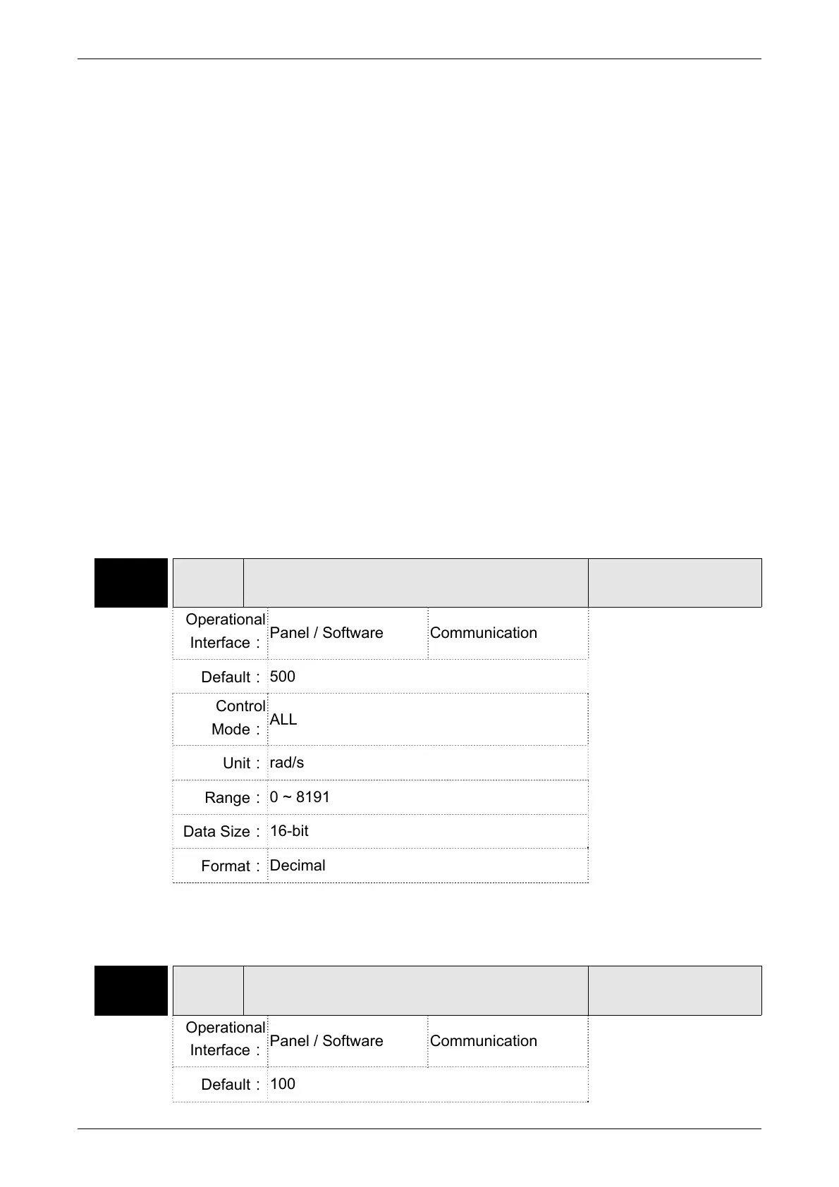
P2-04 KVP Speed Loop Gain
Address: 0208H
0209H
Operational
Interface:
Panel / Software Communication
Related Section:
6.3.6
Default:
500
Control
Mode:
ALL
Unit:
rad/s
Range:
0 ~ 8191
Data Size:
16-bit
Format:
Decimal
Settings:
Increase the value of speed loop gain can enhance the speed
response. However, if the value is set too big, it would easily cause
resonance and noise.
P2-06 KVI Speed Integral Compensation
Address: 020CH
020DH
Operational
Interface:
Panel / Software Communication
Related Section:
6.3.6
Default:
100
 Loading...


