- Failure to comply with above mounting instructions including permitted
orientations and designated clearances may result in derated power output
and may void the warranty. To avoid these issues follow the instructions above!
CAUTION !
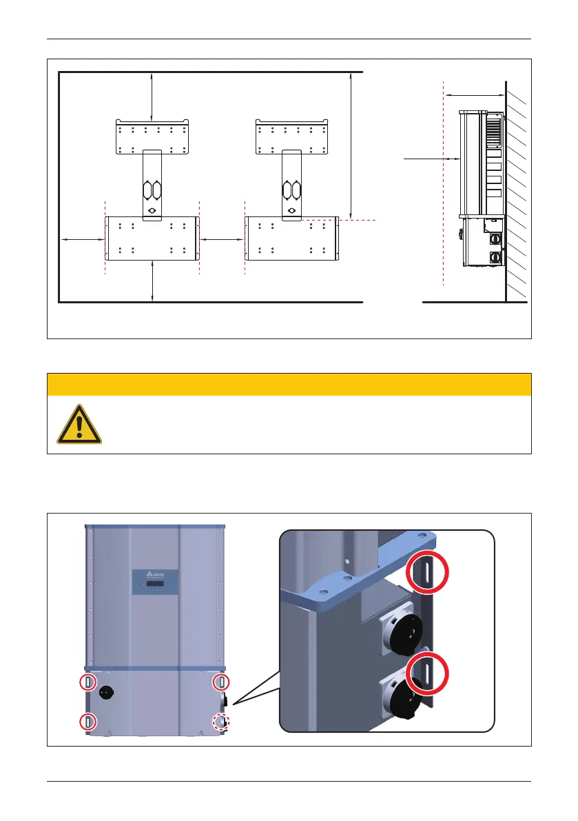
Figure 3-14: Required mounting clearances
> 80cm
[31.5in]
height *
* Keep the height above the highest water level (flood level)
to avoid damage to inverter caused by flood.
> 80cm
[31.5in]
> 33cm
[12.99in]
Wall
Inverter
#2
Inverter
#1
> 5cm
[1.97in]
> 20cm
[7.9in]
> 80cm
[31.5in]
Figure 3-15: Screw locations to secure inverter WB to wall-mounting bracket
After installing the unit on the bracket, secure the wiring box to the bracket with
four screws per Figure 3-15. Tighten the screws to a torque of 40 lbf-in (4.5 N•m)
34
Installation
 Loading...


