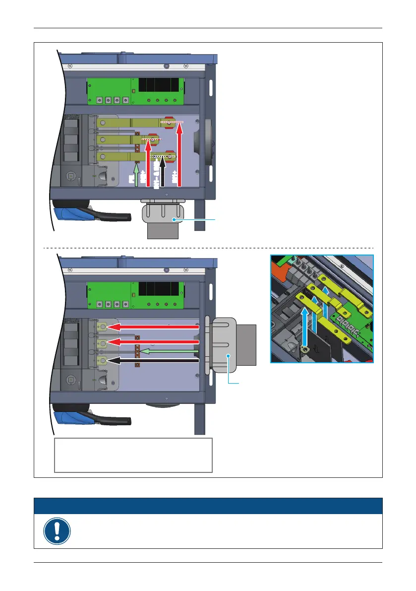
Figure 3-30: Location for DC terminals for M80/60U_121
EMT
Side entry shown using one
2½" (max) EMT for DC array wiring
IN1+
IN2+
IN1
-
&
IN2
-
PE
- Torque for removing/installing bus bar: 159.3 lbf-in (18 N•m)
ATTENTION
EMT
Bottom entry shown using one
2" (max) EMT for DC array wiring
- Allowable conductor size:
1 ~ 3/0 AWG (35 ~ 70mm²)
To secure conductor, tighten the terminal
screw(M6) to a torque of 52 lbf-in (5.9 N•m).
- Allowable PE conductor size:
6 ~ 4 AWG (14 ~ 22mm²)
Torque terminal screw to 26 lbf-in (3 N•m)
- Allowable conductor size:
1 ~ 3/0 AWG (35 ~ 70mm²)
To secure conductor, tighten the terminal
screw to a torque of 159.3 lbf-in (18 N•m).
- Allowable PE conductor size:
6 ~ 4 AWG (14 ~ 22mm²)
Torque terminal screw to 26 lbf-in (3 N•m)
IN1+
IN2+
IN1
-
&
IN2
-
PE
IN1+
IN2+
IN1
-
&
IN2
-
PE
For aluminum cable :
Min./max. Conductor cross-section 35 / 70 mm
2
Tightening torque 159.3 lbf-in (18 N•m)
52
Installation