18
Quick installation guide for solar inverters RPI M6A M8A M10A EU V4 EN 5013221703 00 2017-11-16
The inverter can be connected to a data logger via RS485, e.g.
for monitoring the PV system or changing the inverter settings.
Multiple inverters can be connected in series to a data logger.
Observe the following instructions for ensuring a stable data con-
nection.
Connecting a single inverter to a data logger
► Switch on the RS485 termination resistor.
Connecting multiple inverters to a data logger
► Switch on the RS485 termination resistor at the last inverter
in the chain.
► If the data logger does not have an integrated RS485 ter-
mination resistor then also switch on the RS485 termination
resistor at the rst inverter in the chain.
► Switch off the RS485 termination resistor at all other invert-
ers in the chain.
► Set a different ID at each inverter so that the data logger
can identify the individual inverters.
► Set the same RS485 Baud rate at all inverters.
Cable and wiring requirements
● Shielded twisted-pair cable with solid conductors.
● Cable diameter: 5 mm
● Wire cross-section: 0.25 ... 1.5 mm
2
► Lay the cable with a suitable clearance to the AC and DC
cables to prevent interference in the data connection.
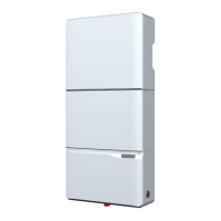
Components of the RS485 card
1
2
1 RS485 (terminal block)
2 DIP switch for the RS485 termination resistor
DIP switch for the RS485 termination resistor
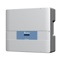
Terminal assignments of the RS485 terminal block
21 43 65
1 VCC (+12 V; 0.5 A)
2 GND
3 DATA+ (RS485)
4 DATA– (RS485)
5 DATA+ (RS485)
6 DATA– (RS485)
Terminal pairs 3/4 or 5/6 can be used. The second terminal pair
is only required when connecting several inverters via RS485.
Data format
Baud rate 9600, 19200, 38400; standard: 19200
Data bits 8
Stop bit 1
Parity Not applicable
The Baud rate can be set on the inverter display after commis-
sioning, see “Baud rate for RS485”, page 23.
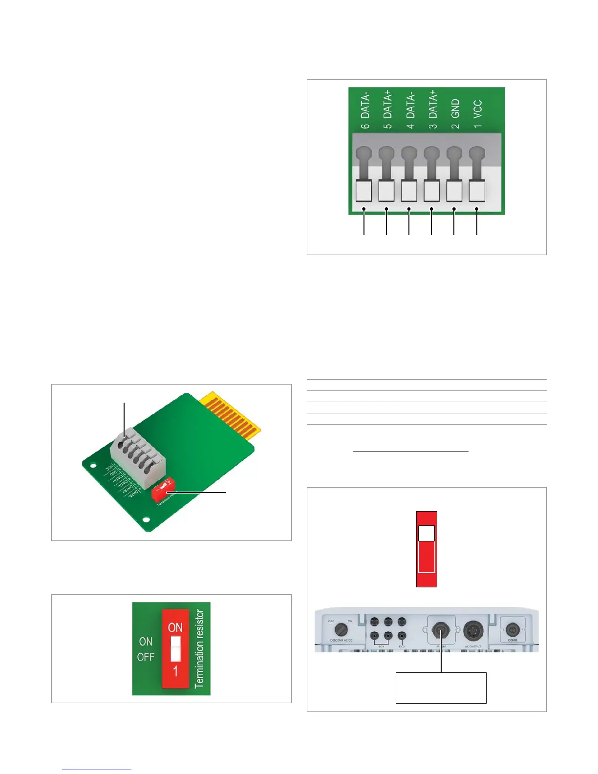
Connecting a single inverter to a data logger
ON
1
RS485
Termination resistor = ON
Data logger
Connecting a data logger via RS485

 Loading...