8
6.5 Ambient temperature
Thesolarinvertercanbeoperatedinanambienttemperaturebetween-25°Cto+60°C.
Thefollowingdiagramillustrateshowthepowersuppliedbythesolarinverterisreducedautoma-
ticallyinaccordancewithambienttemperature.
Thedeviceshouldbeinstalledinawell-ventilated,coolanddrylocation.
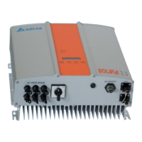
6.6 Grid connection
Thegrid(ACoutput)isconnectedoveraWielandRST25i3SACconnector.Youcanndthecor-
rectallocationonthescrew-typeterminalconnectionoftheconnector.Thesolarinvertermustbe
connectedtothegridoverathree-coreline(L,N,PE).TheconnectedAClinemustbeswitched
potential-freebeforethedisconnectionortheinsertionoftheACconnector.
TheconnectiontotheWielandACconnectormustbemadewithaexiblelineandaconductor
crosssectionofmin.2.5mm²tomax.4.0mm².
AnautomaticcircuitbreakeristobeprovidedinthelineLupstreamofeverydevice,withanominal
currentof16AandtrippingcharacteristictypeB.Inaddition,attentionistobepaidtotheselectivity
ofthefuseunitattachedupstreamoftheautomaticcircuitbreaker.
ThesolarinvertermustbegroundedviatheACconnector’sPEconductor.Todothis,connectthe
PEconductortothedesignatedterminal.Ifyouwishtointegratemorethanoneinverterintothe
installation,pleaseproceedasillustratedinthedrawingsintheappendix.
Pleasenotethecablelengthandthecablecross-section,duetotheriskofundesirabletemperature
riseandpowerlosses.
TheACconnectorisprotectedfromunintentionaldisconnectionbyaclipmechanismwhichcanbe
releasedwithascrewdriver.
6.7 Connection of PV modules
Beforethephotovoltaicsystemisconnected,thepolarityofthePVvoltageattheTycoconnectors
mustbecheckedtoensurethatitiscorrect.
TheconnectionofthePVmoduleisimplementedusingTycoSolarlokconnectors,wheretheDC
negativepoleislocatedontheconnectorupperrowandtheDCpositivepoleontheconnector
lowerrow.Theconnectorsarecodedtopreventyoufromaccidentallypluggingthemintothewrong
terminal.
Pleaseensurethefollowingatalltimes:
•Thatthereisneveranyriskofanyonecomingintocontactwiththesolarinverterconnection
terminals,duetotheriskofdangerousvoltagesacrossthem.
•ThatundernocircumstancesarethePVmodulestobedisconnectedfromthesolarinverterunder
load.Ifadisconnectionshouldbenecessary,rstswitchthegridoffsothatthesolarinverter
cannotabsorbanyfurtherpower.Next,opentheupstreamDCdisconnector.
Themaximuminputvoltageofthesolarinverteris540V.Themaximumcurrentloadofeachindi-
vidualTycoconnectoris18A.