Do you have a question about the Delta SI 5000 and is the answer not in the manual?
Enables easy operation and monitoring of the solar inverter through integrated data display, processing, and communication.
Details the solar inverter's DC/AC converter, MPP tracking, casing, cooling, and microcontroller control systems.
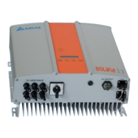
Provides a visual guide to the solar inverter's components, connectors, display panel, and status indicator LEDs.
Guidance on selecting an installation site, considering flammability, resonance, temperature, sunlight exposure, and noise.
Details necessary clearances for convection, grid impedance considerations, and the prescribed vertical installation position.
Instructions for device maintenance, emphasizing keeping it uncovered, cleaning, and the absence of user-serviceable parts.
Instructions for mounting the solar inverter using the provided plate and securing it safely to the wall.
Specifies the operating temperature range and illustrates how ambient temperature impacts the solar inverter's output power.
Details the AC connection procedure using a Phoenix VARIOCON connector, including cable specs and circuit breaker requirements.
Presents a diagram showing the relationship between PV module voltage and the solar inverter's output power capabilities.
Displays efficiency curves for the solar inverter at various input DC voltages and output power levels.
Describes the RS485 interface connection, mating connectors, and the requirement to close all unused interfaces.
Details the electrical connection procedure for the solar inverter, emphasizing not to open the device.
Explains the function of the three front panel LEDs for indicating operational status and reporting faults.
Describes the device's display screen and the function of navigation keys (ESC, ENTER, arrow keys) for user interaction.
Explains how to navigate through display menus and notes the automatic dimming of the display lighting.
Displays instantaneous operating values such as AC power, voltage, current, frequency, and PV inputs.
Provides daily statistics including energy gain, revenue, max/min output power, voltage, current, and frequency.
Shows weekly average values for energy gain, revenue, and operating time of the solar inverter.
Displays monthly average values for energy gain, revenue, and operating time of the solar inverter.
Presents annual average values for energy gain, revenue, and operating time of the solar inverter.
Shows cumulated and maximum/minimum values for energy, revenue, PV inputs, and total operating time.
Allows changing device settings like LCD contrast, backlight, menu mode, ID number, and ISO/GND configuration.
Provides steps for troubleshooting and resetting the solar inverter when error messages appear on the display.
Lists LED status, display messages, their causes, and elimination steps for various faults and operational states.
Illustrates connection diagrams for individual in-plant generation systems in parallel operation with ENS.
Presents connection diagrams for single and multiple PV generators, inverters, meters, and house connections.
| AC nominal voltage | 230 V |
|---|---|
| Output Voltage | 230 V |
| Frequency Range | 50/60 Hz |
| Protection Level | IP65 |
| Cooling Method | Natural convection |
| Efficiency | 97.6% |
| Communication Interface | RS485, Wi-Fi |
| Max. DC power | 5000 W |