14
In order to connect the device electrically, the following procedures must be followed:
1. DC connection: First, connect the PV module strings to the DC disconnect switch (not included
in the scope of delivery).
2. Connect the DC disconnect switch to the solar inverter (ensure correct polarity).
3. AC connection: Next, connect the AC connector to the solar inverter and then to the mains.
4. Before switching on the power, check all feeders and connections one last time.
5. Close DC disconnect.
6. Close the circuit breaker on the AC output side.
7. In case of sufcient PV voltage (UPV > 170 V), the device now goes into the start-up mode.
8. In case of a new installation the time and date have to be set in sub-menu S (Setup) (see page
19, section 7.3.7).
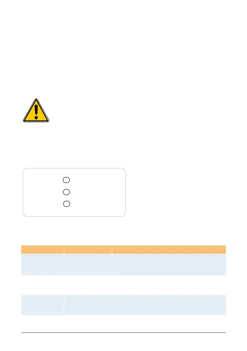
Operation (A)
Earth Fault (B)
Failure (C)
• LED (A), green: „Operation“ displays the
operational state.
• LED (B), red: „Earth Fault“ displays an insula-
tion fault or a PV grounding (GND) fault on
the DC side.
• LED (C), yellow: „Failure“ displays existing
faults internally or externally and whether the
grid feed-in operation has been interrupted.
6.10 LED operation and fault display
Three light-emitting diodes (LEDs), which display the operational state of the solar inverter, are at-
tached on the front:
LED-Status Operational state Explanation
green: <off>
red: <off>
yellow: <off>
Night disconnection.
The input voltage (UPV) is lower than 100 V.
The solar inverter is not feeding power to the grid.
green: <on>
red: <on>
yellow: <on>
Initialization.
Input voltages:
UPV: 100 V to 170 V
(self test ongoing).
green: <ashes>
red: <off>
yellow: <off>
Input- and grid
monitoring.
Starting conditions are tested.
All unoccupied connectors and interfaces must be shut off airtight using the deliv-
ered sealing plugs.