15
7 Operating concept
7.1 The display
The delivery of the solar inverter is implemented ready for operation. No presetting adjustments are
therefore necessary for the user.
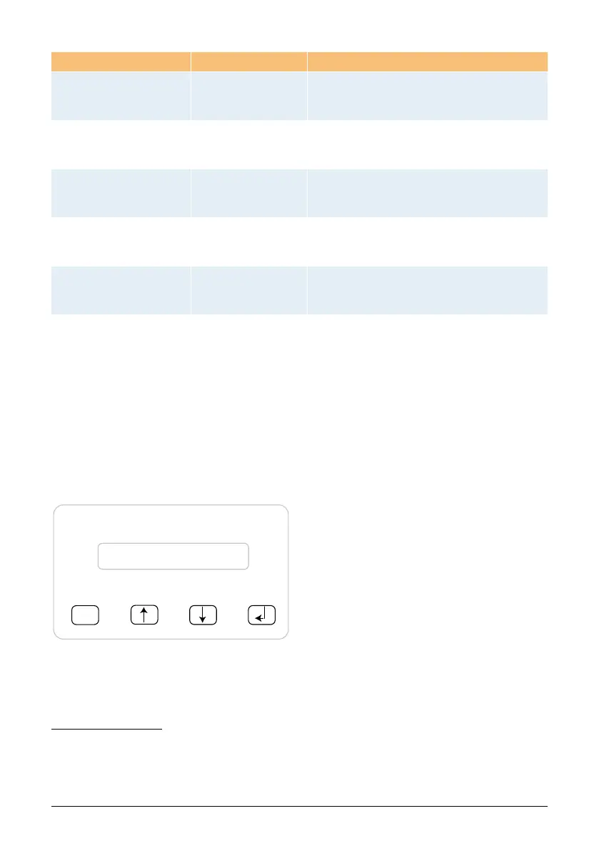
The display on the device indicates different information. The enter keys are used for the adjustment
of the device and for the call-up of information. The indicated measuring data can deviate with a
tolerance of up to 5%.
ESC
(A) (B) (C) (D)
7.2 Navigation in the display
Lighting of the display
Through pressing the ENTER key in automatic operation, the display lighting is implemented. If no
key should be activated within 30 seconds, the display lighting automatically goes out. The setup
menu enables selection between continuous or automatic lighting. Through pressing the ENTER
key, the display lighting is switched on again.
Key (A), ESC: To switch from the menu
items to the main menu and
to exit each sub-menu.
Key (B) and (C): For scrolling in the individual
menu items and/or carrying
out adjustments in the setup
menu.
Key (D), ENTER: ENTER key for changing into
the menu levels and for input
acknowledgement in the
setup menu.
LED-Status Operational state Explanation
green: <on>
red: <off>
yellow: <off>
Feed-in operation.
Normal operational state:
UPV: 170 V to 540 V.
green: <off>
red: <on/off>
yellow: <on/off>
Equipment fault.
Internal or external fault
(interrupted feed).
See also display messages!
green: <on/ashes>
red: <on>
yellow: <off>
Earth fault
The insulation resistance between PV (-)
and/or PV (+) is less than 550 kOHM.
green: <off>
red: <on/off>
yellow: <on>
General error
condition.
Solar inverter is not connected to the grid.
No power is delivered.
See also display messages!
green: <on/off>
red: <on/off>
yellow: <ashes>
Warning message.
You can carry on using the solar inverter.
See also display messages!