Chapter 4 Installation and Wiring
4-9
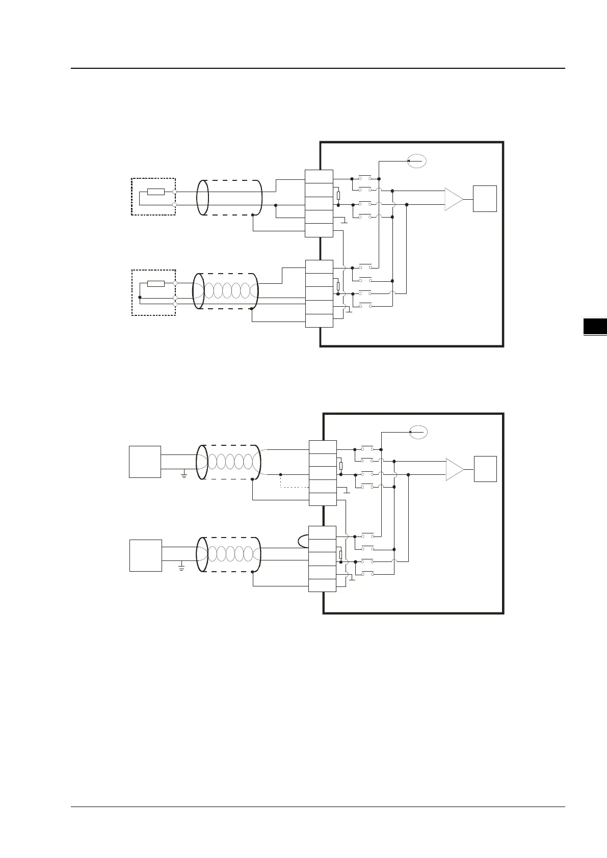
4.2.7 Mixed Analog Input Terminals
Temperature Measurement Input Terminals
Current output
AG2
ADC
AG2
IN A
CH1
L1+
L1-
AG ND
FG
2-Wire
I1+
3-Wire
L2+
L2-
I2+
Pt100/JP t100
/Pt1000
CH2
Ni100/Ni1000/
LG-Ni1000/Cu50/Cu100
Pt100/JP t100/Pt1000
AGND
FG
Shielded
cable*1
Shielded
cable*1
*1. Use shielded cables to isolate the analog input signal cable from other power cables.
Voltage / Current Input Terminals
Current output
AG2
AD C
AG2
IN A
CH1
CH 2
0mV~50mV,
0V~+5V,
0V~+10V
+
-
L1+
L1-
AGND
FG
I1+
0mA~+20mA,
4mA~+20mA
+
-
L1+
L1-
AGND
FG
I1+
Shielded
cable*1
Shielded
cable*1
*1. Use shielded cables to isolate the analog input signal cable from other power cables.
 Loading...