TP70P-211LC1T/TP04P-20EXL1T Operation Manual
4-10
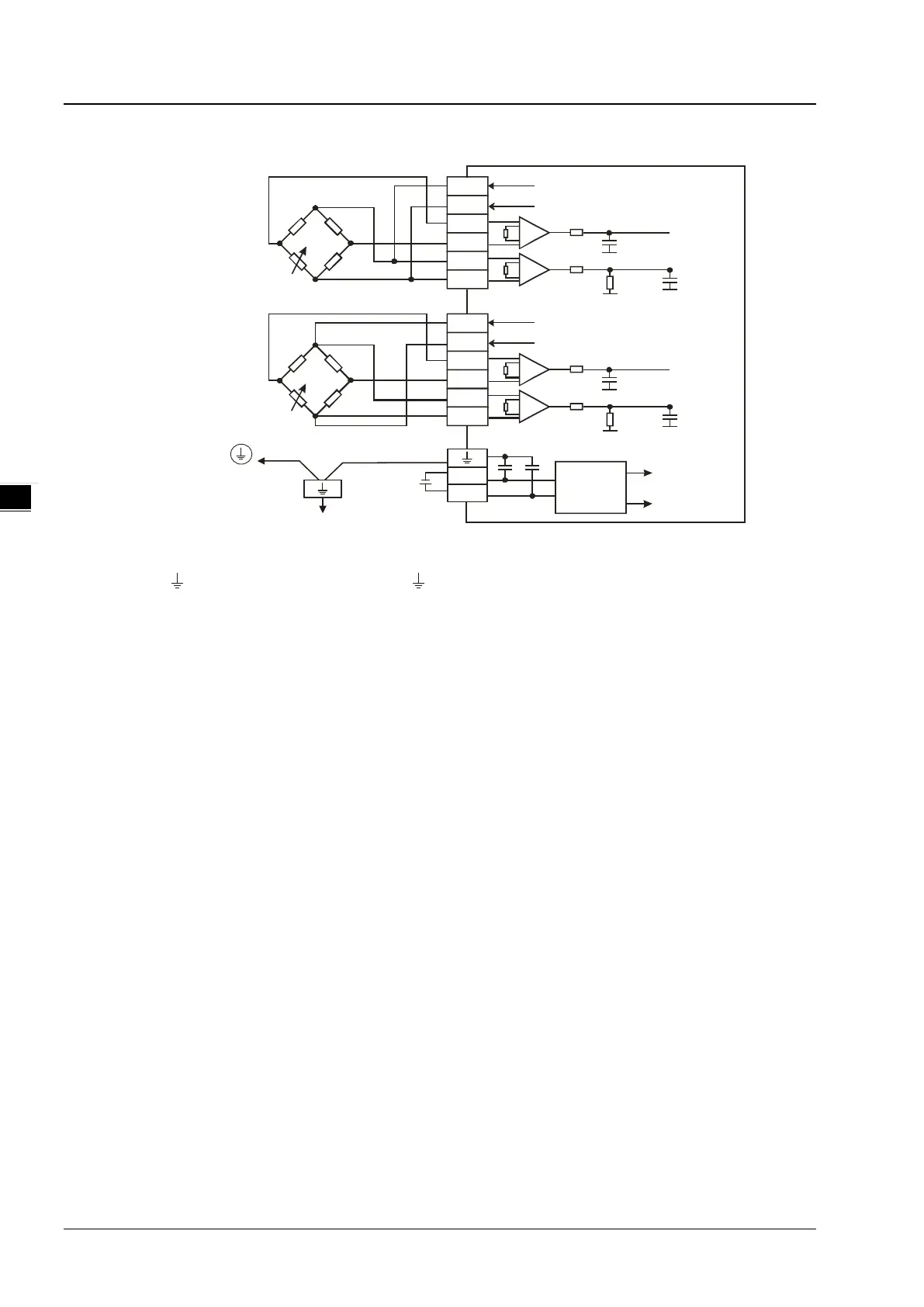
4.2.8 Wiring Load Cell Terminals
CH1
SIG+
SIG-
SEN+
SEN-
EXC+
EXC-
SIG+
SIG-
SEN+
SEN-
EXC+
EXC-
EXC+(2~9.5V)
AG2
DC/DC
converter
4 Wire-
6 Wire-
AG2
AG2 AG2
CH1
EXC+(2~9.5V)
AG2
AG2
AG2
AG2
EXC +(2~9.5V)
AG2
0V
+24V
DC24V
*1
Connected to
on a power supply m odule
System g round
Ground
Impedance: below 100 Ω
*1. Connect the of a power supply module and the of the load cell terminal FE to the system ground and then
ground the system ground or connect the system ground to a distribution box
*2. While connecting multiple load cell modules, the total impedance of the load cell modules should be greater than 40 Ω.
Selecting a Load Cell Sensor
1.
Excitation Voltage / Sensibility (V)
An excitation voltage is the power provided externally for a load cell sensor. The voltage stated in the specification is
the maximum voltage that a sensor can take. The excitation voltage that a load cell module provides is +2 ~ 9.5 V,
and therefore the voltage between +2 ~ 9.5 V is what a sensor can take as its excitation voltage.
2. Eigenvalue
A load cell is based on an electrical circuit called Wheatstone bridge. When a sensor whose resistance varies with
applied force, this small resistance change is magnified by the resistive imbalance produced in the Wheatstone bridge
and thus obtains an output signal proportional SIG+/SIG- to the applied force. The resistive circuit is proportional to
the input voltage supply, and the output of the load cell is often expressed in mV/V, milivolts per volt (supply).
Eigenvalue is a characteristic value for a load cell. The excitation voltage in different eigenvalue modes corresponds
to different eigenvalues. The supported excitation voltage range is 0.5 ~ 256 mV/V. Refer to section 3.1.1 for more
details. Any sensor with up to 256 mV/V of excitation voltage can be used.
The output equation is (applied force divided by maximum rated load) multiples (excitation voltage multiples
eigenvalue).
Example:
Output voltage: 1 mV, Applied force: unknown, Maximum rated load: 10 kg, Excitation voltage: 5 V,
Eigenvalue: 2 mV/V
The equation is 1 mV = (unknown applied force / 10 kg) * (5 V * 2mV/V)
The result: the applied force is 1 kg.
 Loading...