EasyManuals Logo

Delta VFD-B Series User Manual

Delta VFD-B Series
250 pages
To Next Page IconTo Next Page
To Previous Page IconTo Previous Page
Page #221 background imageLoading...
Page #221 background image
Appendix B Accessories_VFD-B Series
Revision 10/2005, BE13, SW V4.08 B-21
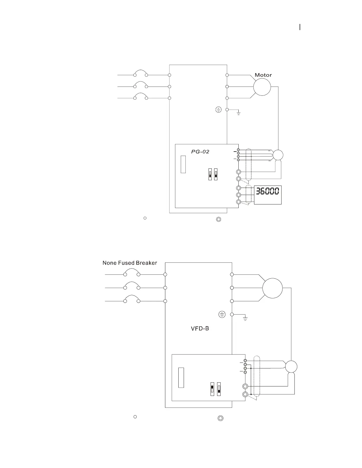
2. Basic Wiring Diagram with RPM Meter Attached.
R/L1
S/L2
T/L3
NFB
U/T1
V/T2
W/T3
IM
3~
VP
COM
VFD-B
+5V
GND
OC
5V
TP
12V
PG-02 and Pulse Generator Connections
A/O
B/O
RPM meter
DCM
PG
A
B
A
B
A
B
A
B
R/L1
S/L2
T/L3
None fused breaker
Main circuit (power) terminals
Control circuit terminals
3. When Pulse Generator (Encoder) is Open Collector type, please refer to following wiring.
R/L1
S/L2
T/L3
NFB
U/T1
V/T2
W/T3
IM
3~
Motor
PG
A
B
VP
DCM
PG-02
5V
GND
A
OC
5V
TP
12V
Factory
Setting
Pulse Generator
Output 5V DC
A
B
R/L1
S/L2
T/L3
Main circuit (power) terminals
Control circuit terminals

Table of Contents

Other manuals for Delta VFD-B Series

Questions and Answers:

Question and Answer IconNeed help?

Do you have a question about the Delta VFD-B Series and is the answer not in the manual?

Delta VFD-B Series Specifications

General IconGeneral
SeriesVFD-B
Cooling MethodFan cooling
Overload Capacity150% for 60 seconds
Braking UnitBuilt-in
Control ModeV/F control, Sensorless Vector Control
CommunicationRS-485
Protection FeaturesOvervoltage, Undervoltage, Overcurrent, Overload, Overtemperature, Short Circuit
Operating Temperature-10°C to +50°C
Storage Temperature-20°C to +60°C
Humidity90% RH (non-condensing)
Altitude1000m (Derating required above 1000m)

Related product manuals