Appendix B Accessories_VFD-B Series
Revision 10/2005, BE13, SW V4.08 B-25
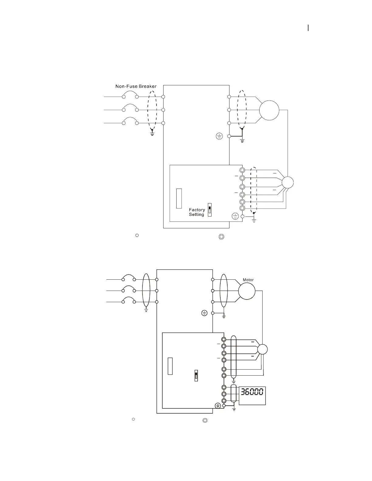
B.3.2.2 PG Card and Pulse Generator (Encoder)
1. Basic wiring diagram
NFB
R/L1
S/L2
T/L3
U/T1
V/T2
W/T3
M
3~
Motor
PG
A
B
12V
0V
PG-03
+12V
GND
OC
TP
Connection between PG-03 and the Encoder
*
Specification of the Encoder
is of the 12V/OC Output
B
B
B
Shield
Terminal
R/L1
S/L2
T/L3
Main circuit (power) terminals
Control circuit terminals
VFD-B
2. Connect Externally with the Encoder of 12V Power Supply and Output Signals to Additional Tachometer
Connection between PG-03 and the Encoder
Non-Fuse Breaker
NFB
R/L1
S/L2
T/L3
U/T1
V/T2
W/T3
M
3~
B
12V
0V
PG-03
GND
A
B
OC
TP
/O
B/O
RPM Meter
ʽ
Specification of the
Encoder is of 12V/OC output,
which could also connect
externally with the RPM wire
ʽ
Power of the should
be supplied by the customers
RPM meter
0V
A
B
A
B
PG
Shield
Terminal
R/L1
S/L2
T/L3
Main circuit (power) terminals
Control circuit terminals
VFD-B

 Loading...


