Chapter 2 Installation and Wiring_VFD-B Series
2-24
Revision 10/2005, BE13, SW V4.08
Terminal Symbol Terminal Function
Factory Settings (SINK)
ON: Connect to DCM
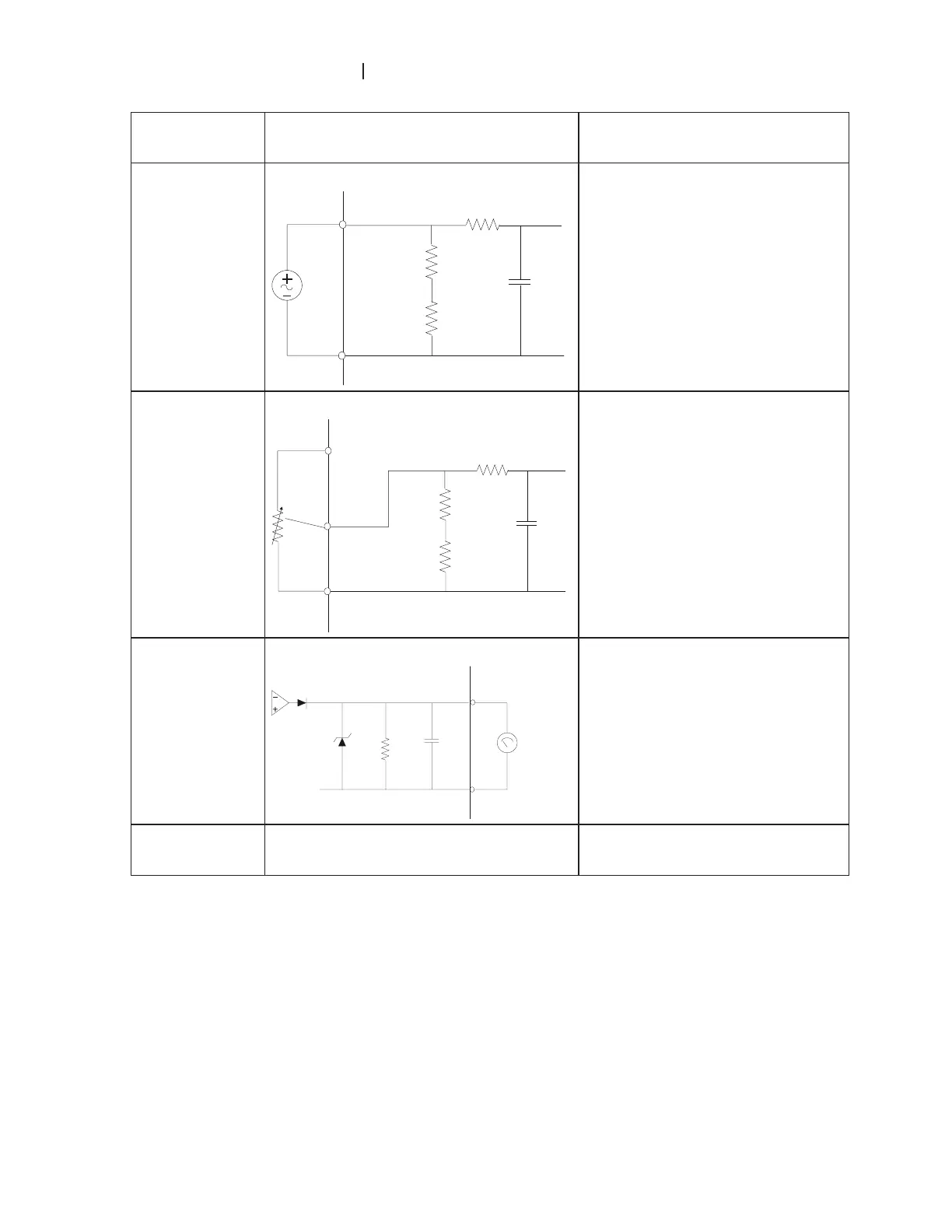
ACI
Analog current Input
ACM
ACI
Internal Circuit
CI circuit
Impedance: 250ȍ
Resolution: 10 bits
Range: 4 ~ 20mA =
0 ~ Max. Output
Frequency (Pr.01-
00)
Selection: Pr.02-00, Pr.02-13,
Pr.10-00
Set-up: Pr.04-11 ~ Pr.04-14
AUI
Auxiliary analog voltage input
ACM
AUI
+10~-10V
Internal Circuit
AUI circuit
Impedance: 47kȍ
Resolution: 10 bits
Range: -10 ~ +10VDC =
0 ~ Max. Output
Frequency (Pr.01-
00)
Selection: Pr.02-00, Pr.02-13,
Pr.10-00
Set-up: Pr.04-15 ~ Pr.04-18
AFM
Analog output meter
Internal Circuit
ACM circuit
FM
CM
0~10V
Max. 2mA
ondometer
0 to 10V, 2mA
Impedance: 470ȍ
Output current 2mA max
Resolution: 8 bits
Range: 0 ~ 10VDC
Function: Pr.03-05
ACM Analog control signal (common) Common for AVI, ACI, AUI, AFM
Control signal wiring size: 18 AWG (0.75 mm
2
) with shielded wire.

 Loading...


